Thin film battery

a technology of thin film and primary batteries, applied in the direction of non-aqueous electrolyte cells, cell components, sustainable manufacturing/processing, etc., can solve the problems of not fully satisfying the above described batteries, the need for thin batteries having flexible housings, etc., and achieve the effect of convenient battery assembly and easy to obtain certain desired surface properties

Active Publication Date: 2011-08-04
RENATA
View PDF8 Cites 20 Cited by
  • Summary
  • Abstract
  • Description
  • Claims
  • Application Information

AI Technical Summary

Benefits of technology

[0024]The first and second polymeric jacket layers which are sealed together to form an outer jacket for the battery help to avoid that water or other liquids enter the cell and establish a conductive path which may result in high self-discharge rates. Furthermore, electrolyte is prevented from escaping the battery, and a dry-out of the battery is thereby avoided. The sealing frame extending circumferentially around the package formed by the anode, the cathode, the separator and the electrolyte, further contributes to the high quality of the sealing. Due to the fact that the sealing frame extends circumferentially around said package, while the first and second polymeric sheets extend circumferentially beyond the frame, a double sealing is provided. The current collectors partly covering the sealing frame form a first sealing zone and the polymeric sheets extending circumferentially beyond said sealing area form a second additional sealing zone.
[0025]According to a preferred embodiment of the invention, the sealing frame is coated with a heat-sealable material. The sealing frame itself can be made of a polymer such as nylon, polyester (PET), polypropylene or any suitable polymer, in particular of PET (poly(ethylene terephthalate), a resin in the polyester family). The coating may consist of hot-melt adhesive EVA (ethylene vinyl acetate) or EMA (ethyl methyl acrylate), or another suitable heat-sealable material. Due to the coating, the frame can easily be sealed to the current collectors and the polymeric sheets. The sealing frame can also consist of two frame elements, each of these elements forming a frame itself. Typically, one such frame element will be arranged on the cathode side, and another one on the anode side during assembly of the battery, and the two frame elements will be bonded together during a final assembly step to form one frame. In case of the use of two frame elements, the separator can arranged with its circumferential edges lying between the two frame elements. It will thus be held in place by the two frame elements when they are bonded together, and any contact between the anode material and the cathode can be avoided in a very reliable and simple way.
[0028]Alternatively, the polymeric jacket layers can also be formed by a polymeric frame which will typically be cut out from a polymeric sheet, and which covers the outer contour of the current collector on which it is arranged. The use of such a frame has the advantage that the whole battery will be thinner than when complete sheets are used, and the additional sealing is limited to those areas where such a sealing is really critical, namely to the outer contour of the current collector. On the other hand, it is easier to obtain certain desired surface properties for the battery when using a whole sheet than when using merely a frame. A complete sheet might thus be the preferred solution when a certain adhesion or a certain appearance is needed.
[0029]The current collectors are preferably metal foils, in particular copper foils. Contact tabs for contacting the battery from the outside can be formed integrally with such a copper foil, and there is thus no need for additional contacts. However, the use of a metallized polymeric film or sheet instead of a metal foil is also possible. According to a preferred embodiment of the invention, at least one of the current collectors is a preformed metal foil having a depression formed in a central area thereof. Such a depression can form a receptacle for a cathode mixture when same is applied to the current collector, and will thus facilitate the assembly of the battery.

Problems solved by technology

However, for certain applications very thin batteries having a flexible housing are needed.
In terms of quality of the sealing and cost-efficiency upon production, the above described batteries are not yet completely satisfying.

Method used


Image

  • Thin film battery
  • Thin film battery
  • Thin film battery

Examples


Embodiment Construction

[0039]It will be appreciated that the following description is intended to refer to two specific embodiments of the invention which have been selected for illustration in the drawings but which are not intended to define or limit the invention, other than in the appended claims.

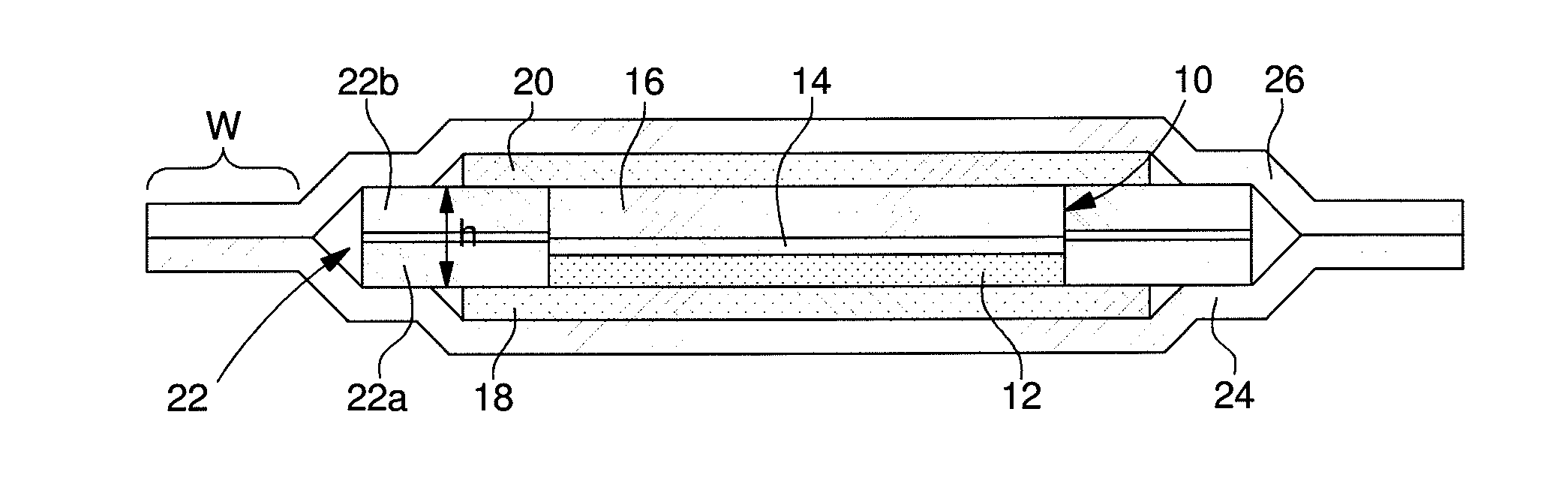
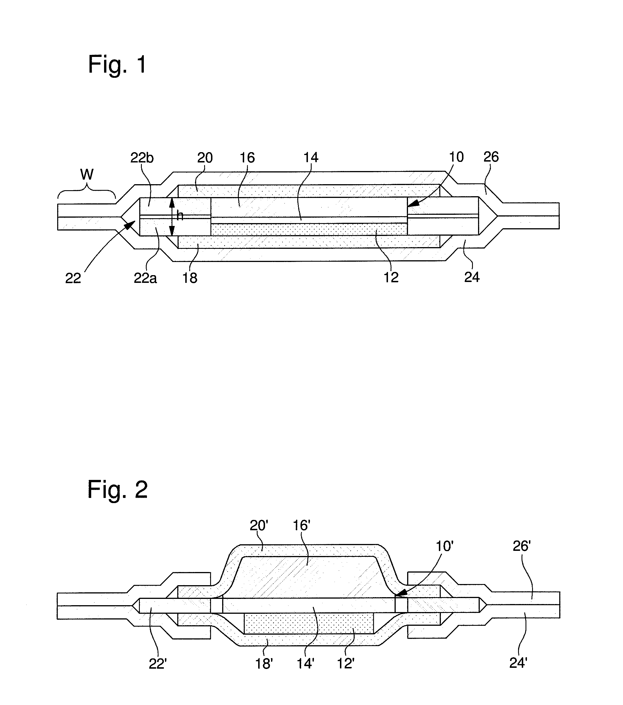
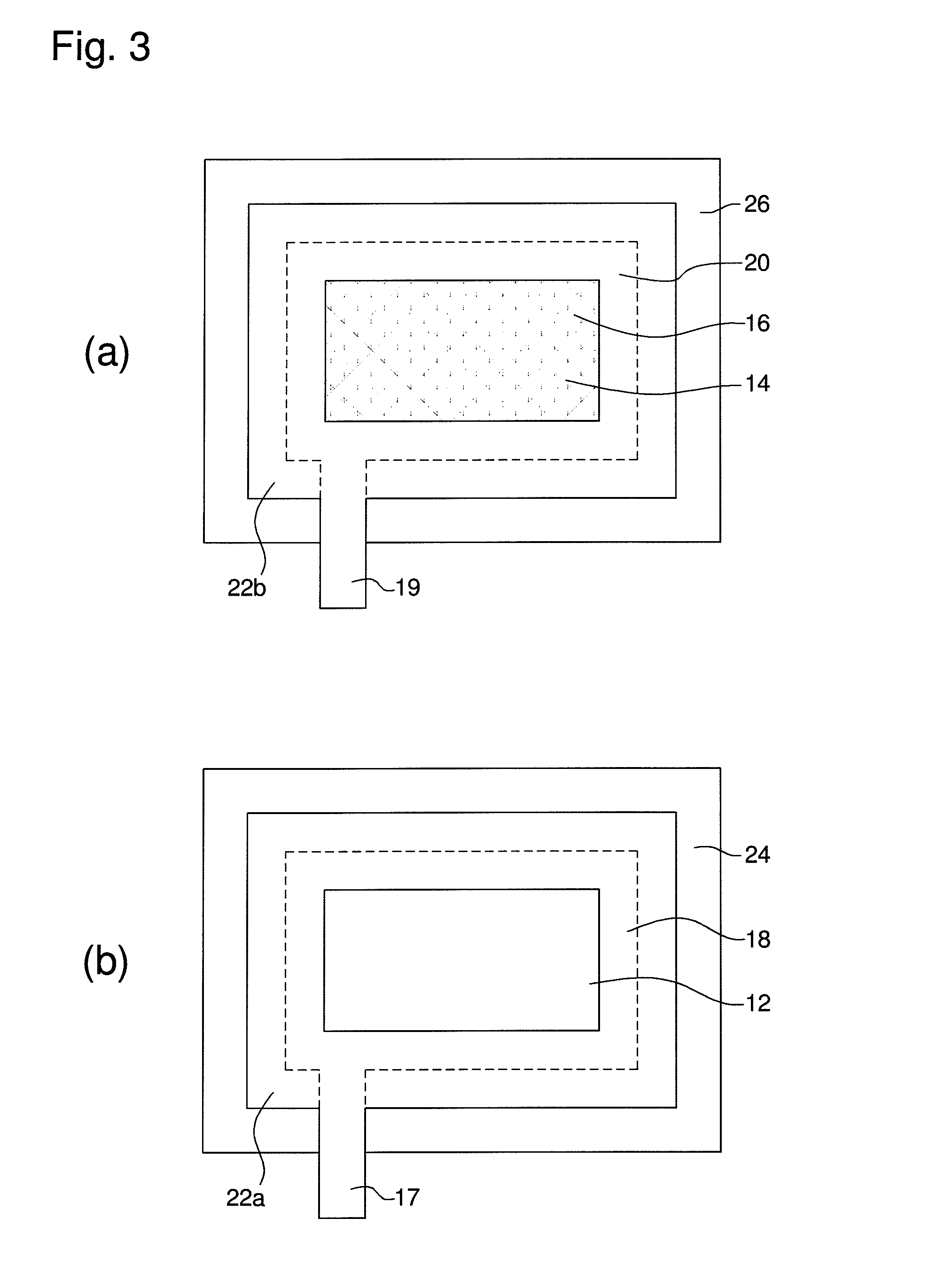
[0040]FIG. 1 shows a cross-section through a flat battery according to the invention, whereas FIGS. 3(a) and 3(b) each show a top view of a preassembled part of the flat battery shown in FIG. 1. More precisely, FIG. 3(a) shows the upper layers of the battery shown in FIG. 1, while FIG. 3(b) shows the lower layers of the same.

[0041]Referring to FIGS. 3(a) and 3(b), a method according to the invention to produce the battery as shown in FIG. 1 will now be described.

[0042]Firstly, the preassembly of the lower layers as shown in FIG. 3(b) will be described.

[0043]In a first step, a first rectangular polymeric sheet 24 being coated with a heat-sealable material on one side is provided. It should be noted that, altho...


PUM

PropertyMeasurementUnit
thicknessaaaaaaaaaa
thicknessaaaaaaaaaa
areaaaaaaaaaaa

Abstract

The present invention concerns a flat battery comprising a package formed by a cathode, an anode, and a separator layer sandwiched between the cathode and the anode, a sealing frame extending circumferentially around said package, a first current collector contacting the anode, and a second current collector contacting the cathode. The first and second current collectors each partly cover the sealing frame in a zone being adjacent to the package. According to the invention, the battery further comprises a first polymeric jacket layer being arranged on the first current collector and a second polymeric jacket layer being arranged on the second current collector, said first and second polymeric jacket layers extending circumferentially beyond the current collectors and beyond the sealing frame and being sealed together to form an outer jacket for the battery. Furthermore, the present invention also concerns a method to produce such a battery.

Description

BACKGROUND OF THE INVENTION[0001]The present invention relates in general to thin film primary batteries.[0002]Electrochemical elements, i.e. batteries, are known in many different physical forms. In most cases, they have a mechanically robust housing and are in the form of round, button or prismatic cells. A positive and a negative electrode, a separator and an electrolyte are arranged in such a cell. The housing of this type of cells is in general composed of steel, a stainless steel alloy or aluminum.[0003]However, for certain applications very thin batteries having a flexible housing are needed. These applications include active radio frequency identification (RFID) tags, PCMCIA cards, smart cards, etc. A battery which shall be used in such applications must be flexible and compact, deliver high energy density and specific energy with a low rate of self discharge, and should be provided with a reliable sealing. The sealing is extremely important, as moisture should be prevented ...

Claims


Application Information

Patent Timeline
Patent Type & Authority Applications(United States)
IPC IPC(8): H01M6/02H01M50/105H01M50/121H01M50/186H01M50/193H01M50/197
CPCH01M2/0207H01M2/0212H01M2/0215H01M2/0267H01M2/027H01M2/0275Y10T29/49115H01M2/08H01M6/005H01M6/40Y10T29/49114Y10T29/4911H01M2/0277H01M50/545Y02P70/50H01M50/105H01M50/186H01M50/121H01M50/193H01M50/197H01M6/14H01M50/557
Inventor WU, HANPFROMMER, STEFAN
Owner RENATA
Why Eureka
Try Eureka