Sealing foil and associated lamp having this foil

a technology of sealing foil and associated lamps, which is applied in the manufacture/treatment of superconductor devices, liquid/solution decomposition chemical coatings, coatings, etc., can solve the problems of high scrap levels during resistance welding and increase the wear of resistance welding electrodes, and achieve high scrap rate and reliable and simple way.

Inactive Publication Date: 2005-11-29
PATENT TREUHAND GESELLSCHAFT FUR ELECTRIC GLUEHLAMPEN MBH
View PDF10 Cites 3 Cited by
  • Summary
  • Abstract
  • Description
  • Claims
  • Application Information

AI Technical Summary

Benefits of technology

[0018]The application of a thin layer of ruthenium (pure or as an alloy) to one side of the second foil makes it possible for extremely fine supply conductors (which may be designed in the form of a coil) to be connected to the foil in a reliable and simple way. Instead of the resistance welding with the aid of a paste (molybdenum or platinum) which has been used hitherto and is only suitable for thick supply conductors or means accepting a very high scrap rate in the case of extremely fine supply conductors, it is now possible to carry out a brazing process (preferably using a eutectic MoRu alloy), for which relatively low temperatures (typically approximately 360° C. less than for pure Ru) are sufficient. Instead of approximately 2300° C., temperatures of only around 1900 to 2000° C. are now reached.

Problems solved by technology

In this very laborious procedure, the welded joints produced between pin and foil by resistance welding are manually placed into a sand-like medium up to the height to which the chromium plating is to take place.
However, the sand-blasting leads to high levels of scrap during resistance welding, since it causes nonconductive Al2O3 particles to remain on the surface of the Mo foil.
Moreover, the wear to the resistance welding electrodes is increased very considerably.

Method used


Image

  • Sealing foil and associated lamp having this foil
  • Sealing foil and associated lamp having this foil
  • Sealing foil and associated lamp having this foil

Examples


Embodiment Construction

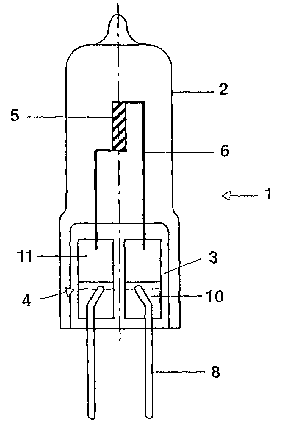
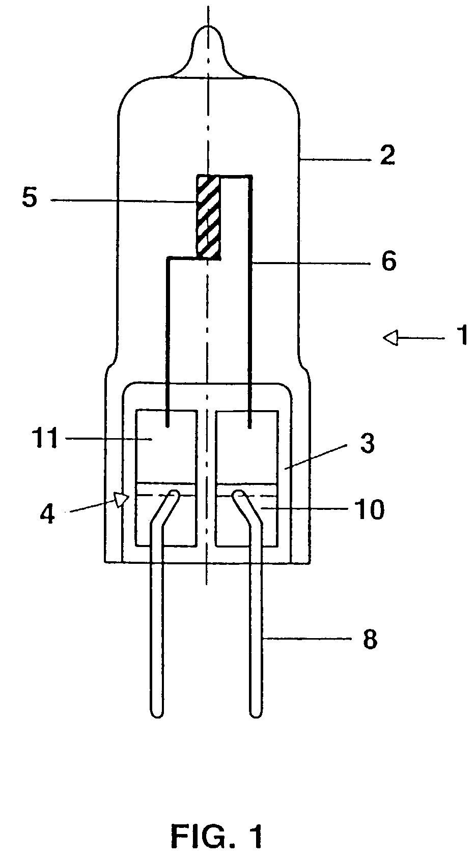
[0022]The exemplary embodiment shown in FIG. 1 is a halogen incandescent lamp 1 (12V for 100 W output) with a lamp bulb 2 made from quartz glass, which is closed off in a gas-tight manner with the aid of a pinch seal 3. Two molybdenum foil stacks 4 are embedded in the pinch seal of the lamp bulb. Inside the lamp bulb there is a double-coiled luminous body 5, of which the single-coiled ends act as inner supply conductors 6. The inner supply conductors are each welded to a molybdenum foil stack 4 embedded in the pinch seal. Two outer supply conductors 8, which are each connected to one of the two molybdenum foil stacks, project out of the pinch seal 3.

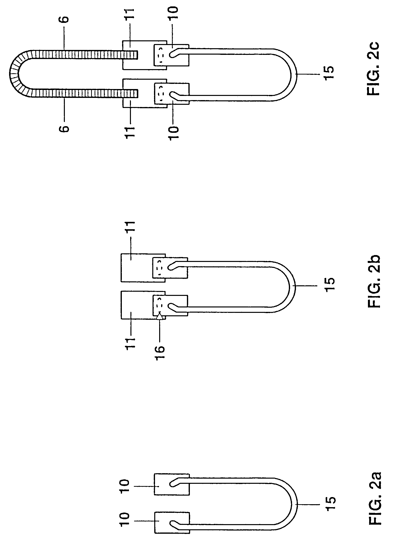
[0023]The two molybdenum foil stacks 4 embedded in the pinch seal each comprises two foils 10, 11. The inner sealing foil 11 is coated with a 60 nm thick eutectic Mo—Ru alloy on one side, specifically the side to which the inner supply conductor 6 is secured. The outer welding foil 10 is coated on both sides with pure Ru with a layer thi...


PUM

PropertyMeasurementUnit
thicknessaaaaaaaaaa
thicknessaaaaaaaaaa
thicknessaaaaaaaaaa

Abstract

Sealing foil for making a lamp (1), comprising a metallic base body made from molybdenum and a coating which has been applied to at least part of the base body and which contains chromium, rhenium or ruthenium, alone or as an alloy, the foil being formed as a stack comprising two parts (10, 11) which have a different coating.

Description

TECHNICAL FIELD[0001]The invention relates to a sealing foil and associated lamp having this foil in accordance with the preamble of claim 1. It deals in particular with molybdenum foils which are used in pinches as are customary for sealing incandescent lamps and discharge lamps.BACKGROUND ART[0002]U.S. Pat. No. 5,021,711 has already disclosed a sealing foil and associated lamp having this foil. To provide better protection against oxidation, the foil is provided with a protective layer of Al, Cr, Si, Ti or Ta. The thickness is 5 to 100 nm.[0003]A similar technique is known from CA -A 1135781, in which layers of Ta, Nb, V, Cr, Ti, Y, La, Hf or Sc are used for the same purpose. The layer thickness is 10 to 200 nm.[0004]In practice, partial chromium-plating is generally used to protect the molybdenum foils from oxidation in the region of the foil-pin welded joint. In this very laborious procedure, the welded joints produced between pin and foil by resistance welding are manually plac...

Claims


Application Information

Patent Timeline
Patent Type & Authority Patents(United States)
IPC IPC(8): C23C18/31H01J9/32H01J61/36H01K1/38H01K1/40H01L39/24
CPCH01J9/326H01K1/38H01J61/368H01J61/04
Inventor BREUER, FRANZBUNK, AXELMITTLER, BODO
Owner PATENT TREUHAND GESELLSCHAFT FUR ELECTRIC GLUEHLAMPEN MBH
Why Eureka
Try Eureka