Status determination device and status determination method

a technology of status determination and status determination, which is applied in the direction of optical apparatus testing, image enhancement, instruments, etc., can solve the problems of economic opportunity loss and increase in operational cos

Inactive Publication Date: 2017-10-26
NEC CORP
View PDF15 Cites 17 Cited by
  • Summary
  • Abstract
  • Description
  • Claims
  • Application Information

AI Technical Summary

Benefits of technology

[0013]The present invention makes it possible to distinctively detect a defect such as cracking, peeling, and an internal cavity by remotely observing a structure.

Problems solved by technology

Accordingly, there arises a problem, such as increase in operational cost due to arrangement of an environment to allow aerial work, and loss in economic opportunity due to traffic control for setting up a work environment.

Method used


Image

  • Status determination device and status determination method
  • Status determination device and status determination method
  • Status determination device and status determination method

Examples


Embodiment Construction

[0045]An example embodiment of the present invention will be described below in detail with reference to the drawings. Note that the example embodiment described below is limited in a technically preferable manner for carrying out the present invention, but is not intended to limit the scope of the invention to the following.

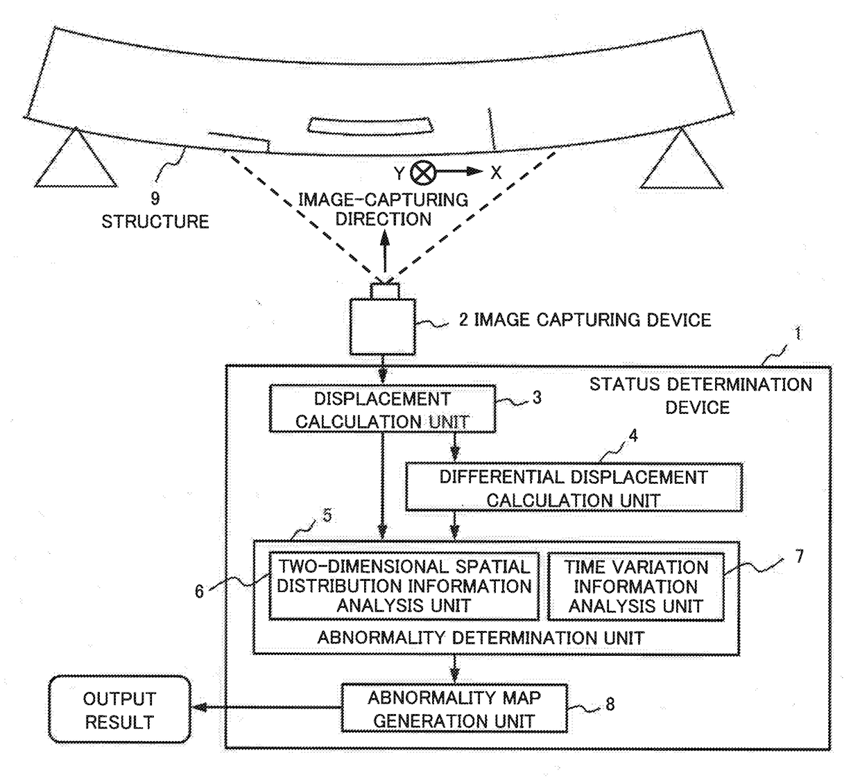
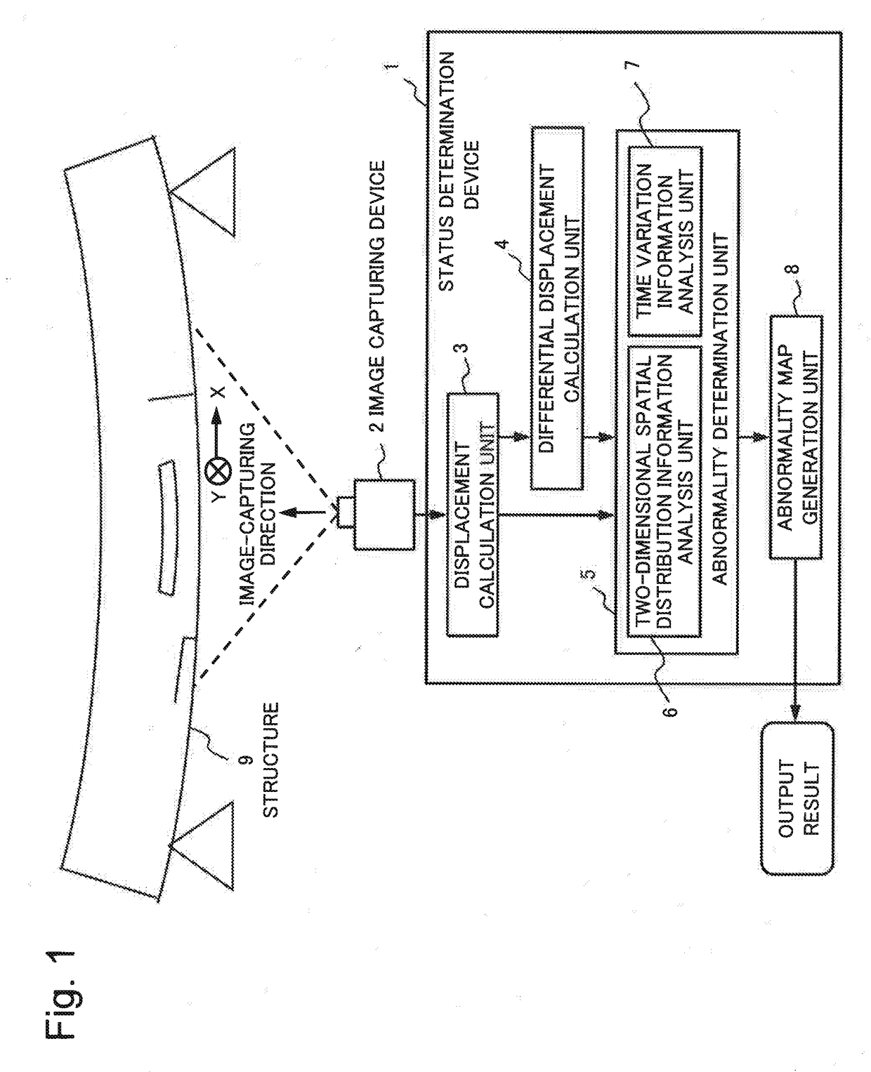
[0046]FIG. 13 is a block diagram illustrating a configuration of a status determination device according to the example embodiment of the present invention. A status determination device 10 according to the present example embodiment includes: a displacement calculation unit 11 that calculates, from time-series images before and after load application to a surface of a structure, a two-dimensional spatial distribution of displacement on the surface of the structure; and an abnormality determination unit 12 that identifies a defect in the structure, based on comparison between the two-dimensional spatial distribution and a spatial distribution of displacement pre...


PUM


Abstract

The present invention addresses the problem of making it possible to distinguish and detect cracking, peeling, internal cavities, and other defects through the remote observation of a structure. A status determination device according to the present invention is provided with a displacement calculation unit for calculating a two-dimensional spatial distribution of the displacement of a structure surface from time series images of the structure surface before and after load application and an abnormality determination unit for identifying flaws in the structure on the basis of a comparison of the two-dimensional spatial distribution and an already provided spatial distribution of displacement.

Description

TECHNICAL FIELD[0001]The present invention relates to a device for determining a status of a structure and a method for determining a status of a structure.BACKGROUND ART[0002]It is known that, in a concrete structure such as a tunnel and a bridge, cracking, peeling, an internal cavity and the like occurring on a surface of a structure affect soundness of the structure. Thus, in order to accurately determine the soundness of the structure, it is necessary to accurately detect the cracking, the peeling, the internal cavity and the like.[0003]Detection of cracking, peeling, an internal cavity and the like of a structure has been performed through visual inspection and hammering inspection by an inspector, and for inspection, the inspector needs to approach the structure. Accordingly, there arises a problem, such as increase in operational cost due to arrangement of an environment to allow aerial work, and loss in economic opportunity due to traffic control for setting up a work enviro...

Claims


Application Information

Patent Timeline
Patent Type & Authority Applications(United States)
IPC IPC(8): G01B11/16G01M5/00G01M11/08G06T7/246G01B11/25
CPCG01B11/165G01M11/081G01B11/2518G06T7/246G01M5/005G01B11/16G01N19/08G06T7/001G06T2207/30108G06T7/254G01M5/0008G01M5/0033G01M5/0091
Inventor IMAI, HIROSHI
Owner NEC CORP
Why Eureka
Try Eureka