Rotor of rotary electric machine

Inactive Publication Date: 2017-10-26
TOYOTA JIDOSHA KK
View PDF7 Cites 7 Cited by
  • Summary
  • Abstract
  • Description
  • Claims
  • Application Information

AI Technical Summary

Benefits of technology

[0019]According to the present invention, it is possible to effectively utilize both reluctance torque and magnet torque, as it is possible to keep low the magnetic resistance of both of the q axis magnetic path and the d axis magnetic path. Further, it is possible to prevent dec

Problems solved by technology

In a permanent magnetic synchronous rotary electric machine including a permanent magnet embedded inside a rotor core, when the temperature of the rotor increases as the rotary electric machine is driven, the magnetic performance is deteriorated, which res

Method used


Image

  • Rotor of rotary electric machine
  • Rotor of rotary electric machine
  • Rotor of rotary electric machine

Examples


Embodiment Construction

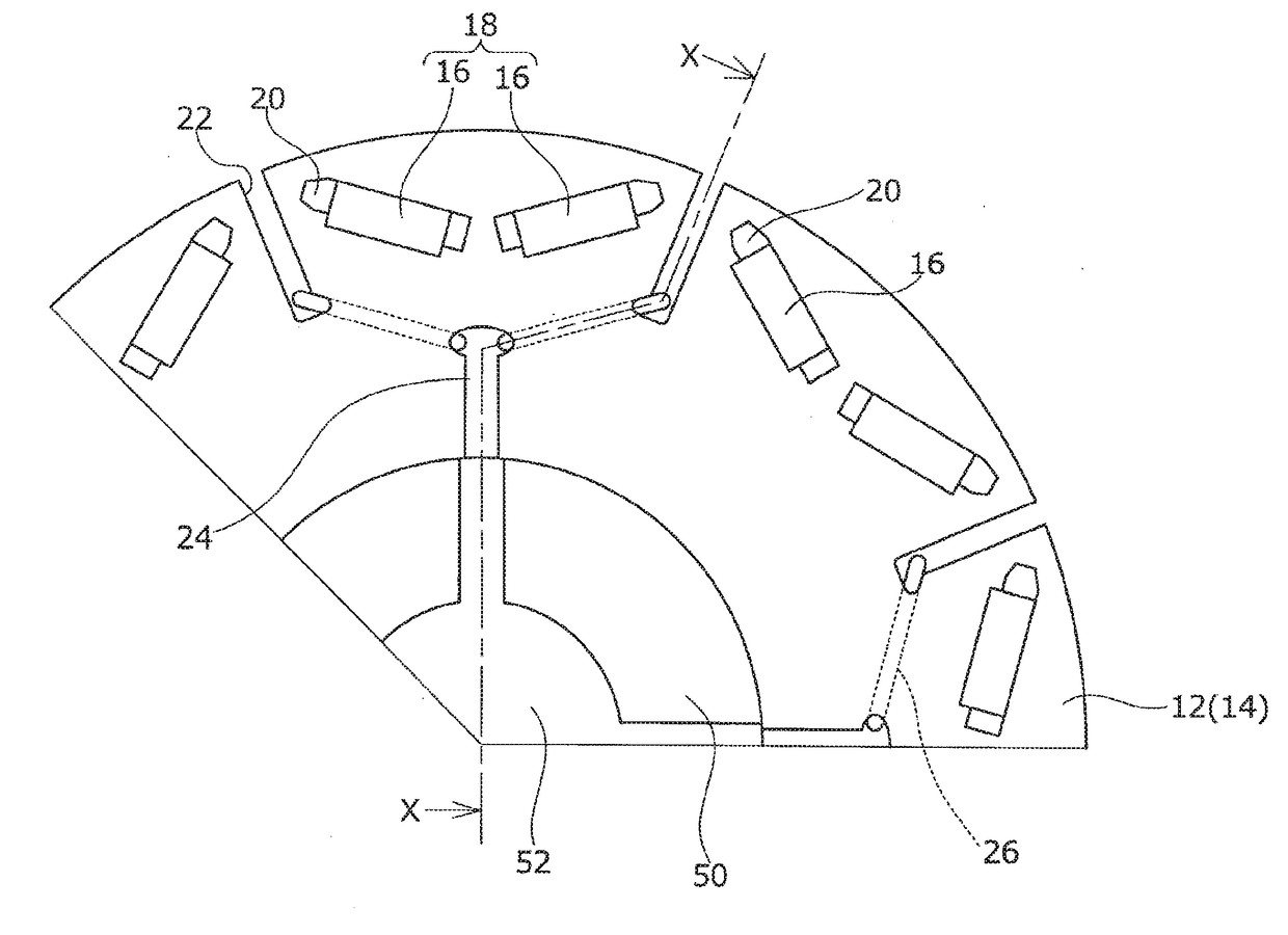
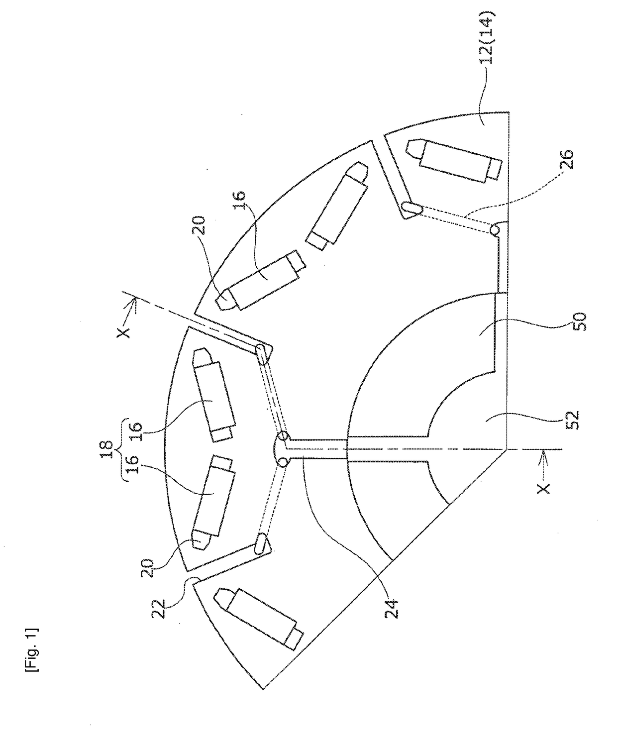
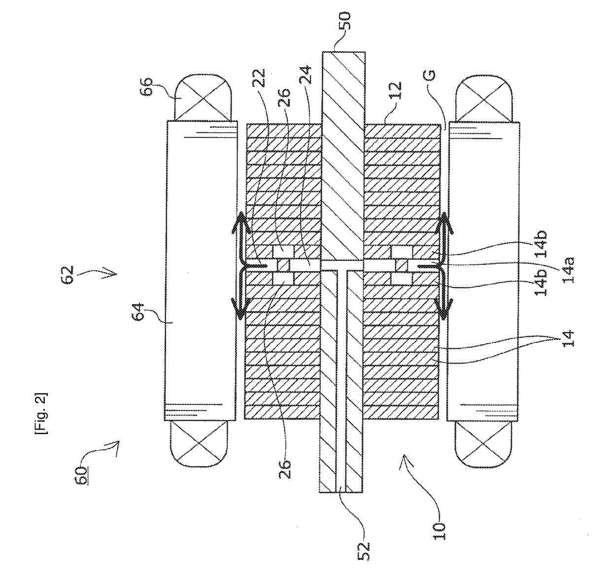
[0031]In the following, embodiments of the present invention will be described with reference to the drawings. FIG. 1 is a horizontal cross sectional view of a rotor 10 used in a rotary electric machine 60 according to a first embodiment of the present invention. FIG. 2 is a cross sectional view of the rotary electric machine 60 along the line X-X in FIG. 1. For readily understanding of the invention, the length in the diameter direction in FIG. 2 is not the same proportion as that in FIG. 1, but is slightly exaggerated, and the thickness or the like of each electromagnetic steel plate is different proportion from the actual thickness.

[0032]The rotary electric machine 60 in this embodiment is a permanent magnetic synchronous rotary electric machine including a permanent magnet 16 embedded inside a rotor core 12. The rotary electric machine 60 includes the rotor 10 and a stator 62. The stator 62 comprises a substantially annular stator core 64 having a plurality of teeth formed along...


PUM


Abstract

In a rotor core (12) of a rotor (10), a core interior refrigerant path is formed. The core interior refrigerant path includes a first refrigerant path (22) formed for every magnetic pole and extending along each q axis from the outer circumferential end of the rotor core (12) toward the inner circumference of the rotor core (12); a second refrigerant path (24) formed for every other magnetic pole and extending along a d axis from the inner circumferential end of the rotor core (12) to a position closer to the inner circumference than the permanent magnet (16) is; and a third refrigerant path (26) extending in a rotor circumferential direction at a position displaced in the rotor shaft direction relative to the first refrigerant path (22) to provide fluid communication between the first refrigerant path (22) and the second refrigerant path (24).

Description

TECHNICAL FIELD[0001]The present invention relates to a rotor of a rotary electric machine including a rotor core, and a permanent magnet embedded near the outer circumference of the rotor core.BACKGROUND ART[0002]In a permanent magnetic synchronous rotary electric machine including a permanent magnet embedded inside a rotor core, when the temperature of the rotor increases as the rotary electric machine is driven, the magnetic performance is deteriorated, which results in not only decrease of torque and efficiency, but also demagnetization of the permanent magnet when the temperature becomes high. Employment of a magnet having high coercivity can avoid the problem of demagnetization. However, in such a case, it is necessary to increase the content rate of heavy rare earth elements, which increases cost.[0003]In view of the above, conventionally, various structures have been suggested in order to cool a rotary electric machine. For example, Patent Document 1 discloses a technique fo...

Claims


Application Information

Patent Timeline
IPC IPC(8): H02K1/32H02K1/27
CPCH02K1/276H02K1/32H02K1/2766
Inventor OKOUCHI, TOSHINORIHATTORI, HIROYUKI
Owner TOYOTA JIDOSHA KK
Why Eureka
Try Eureka