Antenna cover, use of an antenna cover, adapter for connecting two antenna covers and method for producing a lens-shaped antenna cover

a technology for antenna covers and antennas, applied in antenna details, antenna housings, radiating elements, etc., can solve problems such as difficult injection molding production, and achieve the effect of facilitating the joining of lens halves and constant wall thickness

Active Publication Date: 2017-11-16
VEGA GRIESHABER GMBH & CO
View PDF8 Cites 3 Cited by
  • Summary
  • Abstract
  • Description
  • Claims
  • Application Information

AI Technical Summary

Benefits of technology

[0035]The fins can be formed on the first base body as concentric circles, or also as fins running in parallel or fins running linearly. In the production of cylindrical lenses in particular, fins running in parallel may be used over the length of the lens as joining contours. The use of fins running in parallel can facilitate the joining of the lens halves in the event of limited heights, in that the lens parts are pushed onto one another, while for assembling lens parts with fins arranged with circular symmetry, raising of the lens parts is necessary.
[0036]According to another aspect of the present invention, the fins may be arranged in a comb-like manner along the width of the first base body. In the case of fins arranged in a circular shape in particular, a cross section through the joining contour may have a comb-like shape. The comb-like shape can enable constant wall thicknesses to be maintained.

Problems solved by technology

On account of the different thicknesses of a lens, however, production by injection moulding is difficult and lenses are therefore produced as turned parts.

Method used


Image

  • Antenna cover, use of an antenna cover, adapter for connecting two antenna covers and method for producing a lens-shaped antenna cover
  • Antenna cover, use of an antenna cover, adapter for connecting two antenna covers and method for producing a lens-shaped antenna cover
  • Antenna cover, use of an antenna cover, adapter for connecting two antenna covers and method for producing a lens-shaped antenna cover

Examples


Embodiment Construction

[0057]The drawings are schematic and are not to scale. In the following description of FIGS. 1 to 9, the same reference numerals are used for identical or corresponding elements.

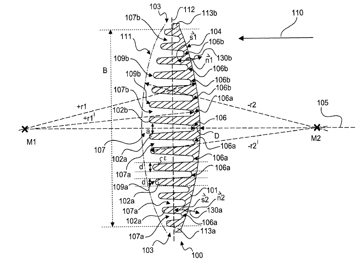
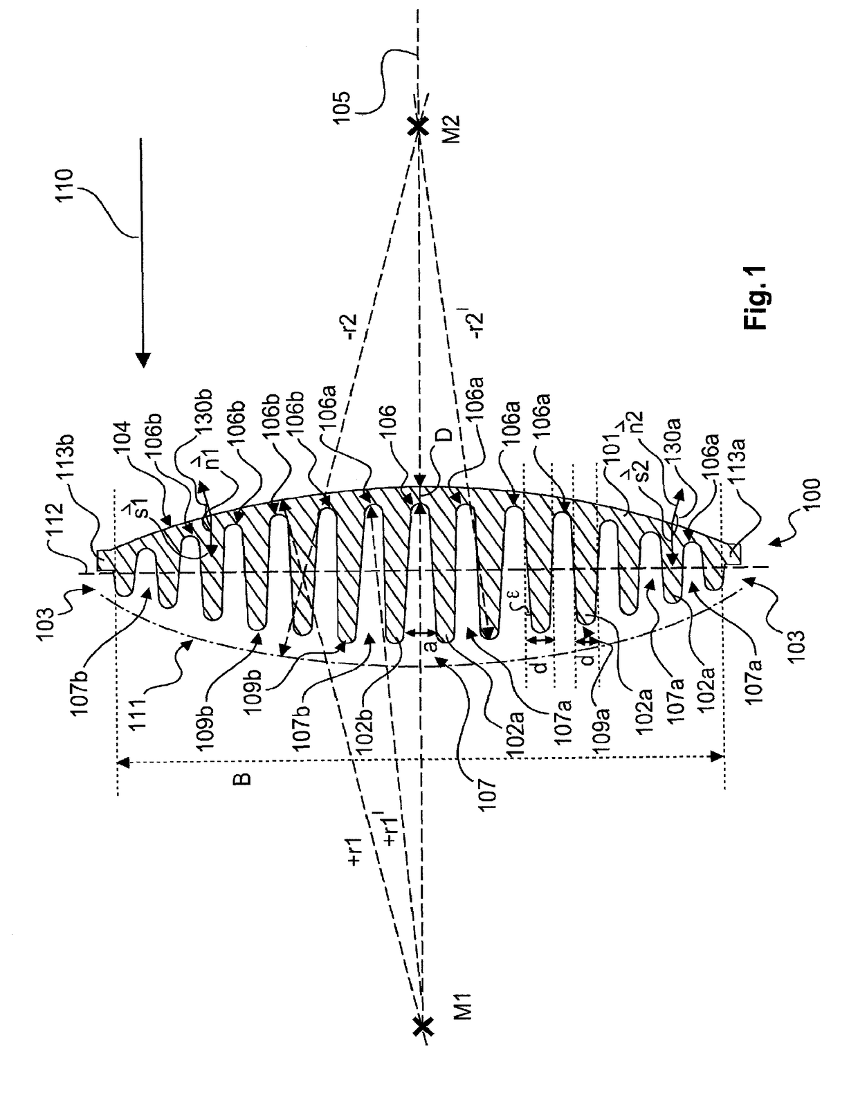
[0058]FIG. 1 is a cross section through an antenna cover according to an exemplary embodiment of the present invention. The antenna cover 100 has a first base body 101 and an even number of at least two first fins 102a, 102b. The even number of at least two fins forms the joining contour 103, joining means 103 or the attachment means 103. The base body 101 has the curved surface 104, which in an assembled state is one of the refraction surfaces of the finished lens. The refraction surface 104 can ensure a deflection of radiation 110 which passes through the antenna cover 100. The base body 101 and fins 102a, 102b are formed in one piece or are monolithic, as they are produced by injection moulding and form a common body of the antenna cover 100.

[0059]In the example of FIG. 1, the curved surface 104 is formed...


PUM


Abstract

An antenna cover is provided, including a first base body and at least two first fins arranged on the first base body, the first base body having a curved surface, the two first fins being arranged symmetrically to a longitudinal axis of symmetry of the antenna cover and extending substantially parallel to the longitudinal axis of symmetry, the at least two first fins having a width that tapers as a distance from the first base body increases, and the at least two first fins being arranged with a spacing that corresponds substantially to the width of the at least two fins. A method for producing a lens-shaped antenna cover is also provided.

Description

FIELD OF THE INVENTION[0001]The present invention relates to the technical field of fill level measurement. In particular, the present invention relates to an antenna cover, to the use of an antenna cover for the construction of a lens, to an adapter and to a method for producing a lens-shaped antenna cover.TECHNOLOGICAL BACKGROUND[0002]Fill level measuring devices often use antennas to bundle electromagnetic rays and to specify a direction of propagation of the electromagnetic rays, which are transmitted in the direction of a filling material. The reflections of the electromagnetic rays on the surface of a filling material are utilised to determine a fill level or the height of a bulk material. A filling material can thus be a material which is put into a container or a material that lies on an open space as a bulk material. Since the antennas are often implemented as horn antennas and are also frequently used in dirty environments, covers are used for the horn antennas in order to...

Claims


Application Information

Patent Timeline
Patent Type & Authority Applications(United States)
IPC IPC(8): H01Q1/42H01Q1/22H01Q13/02H01Q15/08
CPCH01Q1/422H01Q1/225H01Q13/02H01Q15/08H01Q19/062
Inventor LENK, FRITZ
Owner VEGA GRIESHABER GMBH & CO
Why Eureka
Try Eureka