Method and article for emitting radiation from a surface

Active Publication Date: 2017-12-14
SABIC GLOBAL TECH BV
View PDF2 Cites 8 Cited by
  • Summary
  • Abstract
  • Description
  • Claims
  • Application Information

AI Technical Summary

Problems solved by technology

These devices suffer from one or more of an obstructed view through the device, opacity, insufficiently uniform intensity of

Method used


Image

  • Method and article for emitting radiation from a surface
  • Method and article for emitting radiation from a surface
  • Method and article for emitting radiation from a surface

Examples


embodiment 1

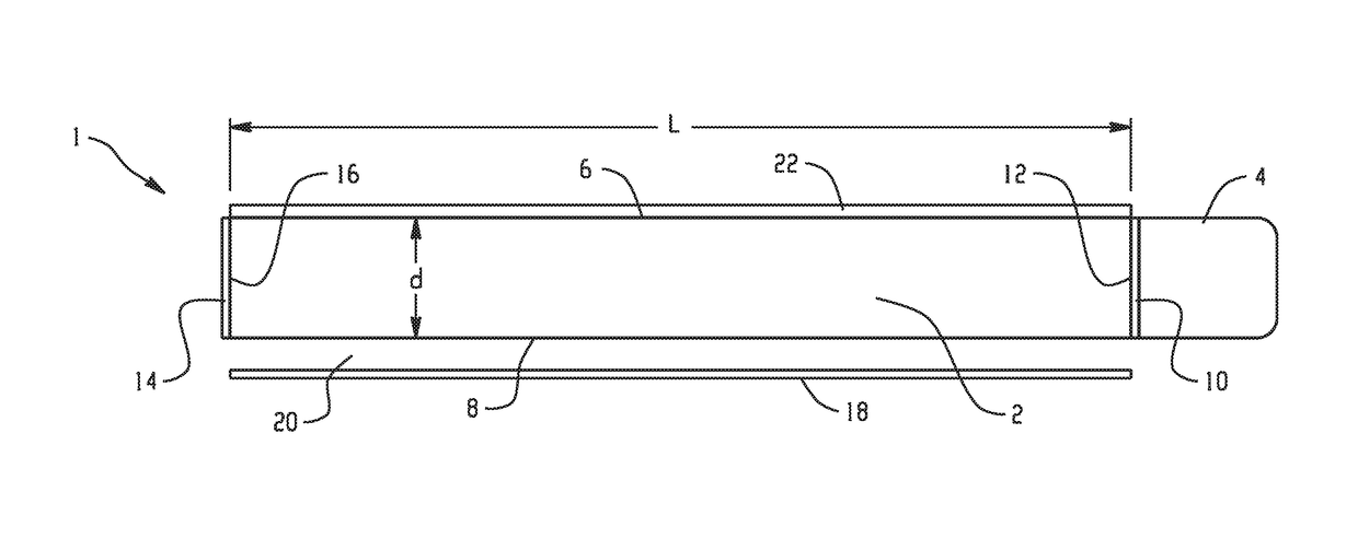
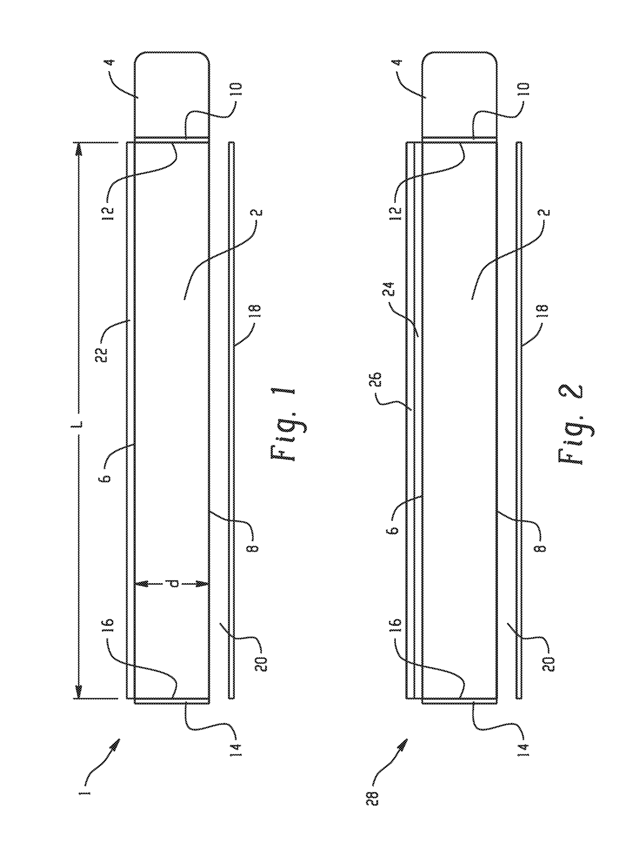
[0077]A radiation emitting device comprising: a radiation emitting layer comprising a host material and a luminescent agent; and a radiation source that emits a source radiation; wherein the radiation emitting layer comprises an edge and two broad surfaces, wherein the edge has a height of d and the broad surfaces have a length L, wherein length L is greater than height d, and the ratio of the length L to the height d is greater than or equal to 10; and wherein the radiation source is coupled to the edge, wherein the source radiation is transmitted from the radiation source through the edge and excites the luminescent agent, whereafter the luminescent agent emits an emitted radiation, wherein at least a portion of the emitted radiation exits through at least one of the broad surfaces through an escape cone.

embodiment 2

[0078]The device of Embodiment 1, wherein the radiation emitted from one or both of the broad surfaces is uniform such that the measured radiation at all locations on a broad surface is within 40%, specifically, 30%, more specifically, 20% of the average radiation being emitted from the broad surface.

embodiment 3

[0079]The device of any of the preceding Embodiments, further comprising one or more of an edge mirror, a selectively reflecting edge mirror, and a surface mirror.


PUM


Abstract

In an embodiment, a radiation emitting device comprises a radiation emitting layer comprising a host material and a luminescent agent; and a radiation source that emits a source radiation; wherein the radiation emitting layer comprises an edge and two broad surfaces, wherein the edge has a height of d and the broad surfaces have a length L, wherein length L is greater than height d, and the ratio of L to d is greater than or equal to 10; and wherein the radiation source is coupled to the edge, wherein the source radiation is transmitted from the radiation source through the edge and excites the luminescent agent, whereafter the luminescent agent emits an emitted radiation, wherein at least a portion of the emitted radiation exits through at least one of the broad surfaces through an escape cone.

Description

BACKGROUND[0001]Radiating devices have been developed for applications such as defrosting, defogging, and / or deicing a surface; illumination; and for self-cleaning surfaces. These devices suffer from one or more of an obstructed view through the device, opacity, insufficiently uniform intensity of the emitted radiation, insufficient intensity of emitted radiation far from the perimeter of the device, and low efficiency. A radiation emitting device that is able to overcome one or more of these drawbacks is desirable.BRIEF DESCRIPTION[0002]Disclosed herein is a radiation emitting device and a method of emitting radiation therefrom.[0003]In an embodiment, a radiation emitting device comprises a radiation emitting layer comprising a host material and a luminescent agent; and a radiation source that emits a source radiation; wherein the radiation emitting layer comprises an edge and two broad surfaces, wherein the edge has a height of d and the broad surfaces have a length L, wherein len...

Claims


Application Information

Patent Timeline
IPC IPC(8): F21V8/00C09K11/06C25B1/00C09K11/08
CPCG02B6/0003C25B1/003C09K11/08C09K11/06G02B6/0031C25B1/55C09K11/7706C09K11/88
Inventor GASWORTH, STEVEN MARC
Owner SABIC GLOBAL TECH BV
Why Eureka
Try Eureka