Light-emitting element, display device, electronic device, and lighting device
a technology of light-emitting elements and electronic devices, which is applied in the direction of luminescent compositions, organic semiconductor devices, chemistry apparatus and processes, etc., can solve the problems of difficult design of light-emitting materials that meet these two requirements, and achieve the effect of reducing driving voltage and increasing light emission efficiency
- Summary
- Abstract
- Description
- Claims
- Application Information
AI Technical Summary
Benefits of technology
Problems solved by technology
Method used
Image
Examples
embodiment 1
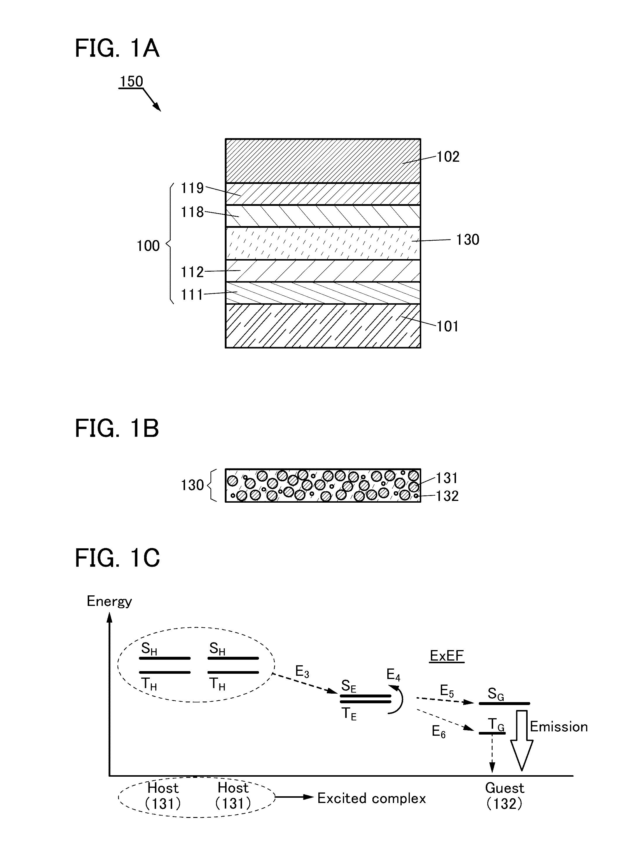
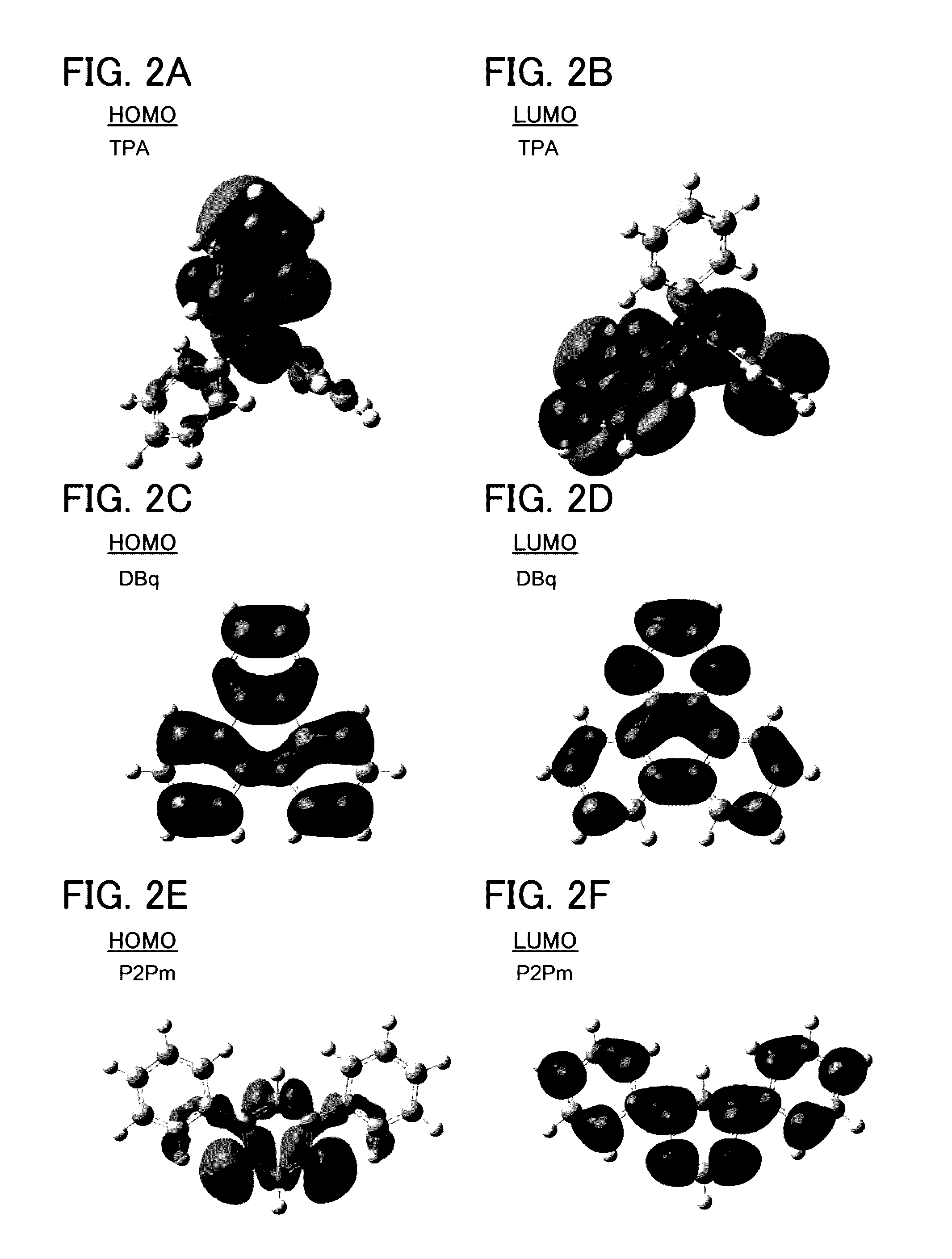
[0091]In this embodiment, a light-emitting element of one embodiment of the present invention will be described below with reference to FIGS. 1A to 1C, FIGS. 2A to 2F, FIGS. 3A to 3D, FIGS. 4A to 4F, FIGS. 5A to 5D, FIGS. 6A to 6D, FIGS. 7A to 7D, FIGS. 8A to 8D, FIGS. 9A to 9D, and FIGS. 10A to 10D.
[0092]First, a structure of the light-emitting element of one embodiment of the present invention will be described below with reference to FIGS. 1A to 1C.
[0093]FIG. 1A is a schematic cross-sectional view of a light-emitting element 150 of one embodiment of the present invention.
[0094]The light-emitting element 150 includes a pair of electrodes (an electrode 101 and an electrode 102) and an EL layer 100 between the pair of electrodes. The EL layer 100 includes at least a light-emitting layer 130.
[0095]The EL layer 100 illustrated in FIG. 1A includes functional layers such as a hole-injection layer 111, a hole-transport layer 112, an electron-transport layer 118, and an electron-injection...
embodiment 2
[0253]In this embodiment, a light-emitting element having a structure different from that described in Embodiment 1 and light emission mechanisms of the light-emitting element are described below with reference to FIGS. 11A to 11C. In FIG. 11A, a portion having a function similar to that in FIG. 1A is represented by the same hatch pattern as in FIG. 1A and not especially denoted by a reference numeral in some cases. In addition, common reference numerals are used for portions having similar functions, and a detailed description of the portions is omitted in some cases.
[0254]FIG. 11A is a schematic cross-sectional view of a light-emitting element 152 of one embodiment of the present invention.
[0255]The light-emitting element 152 includes a pair of electrodes (an electrode 101 and an electrode 102) and an EL layer 100 between the pair of electrodes. The EL layer 100 includes at least a light-emitting layer 140.
[0256]Note that the electrode 101 functions as an anode and the electrode 1...
embodiment 3
[0302]In this embodiment, light-emitting elements having structures different from those described in Embodiments 1 and 2 and light emission mechanisms of the light-emitting elements are described below with reference to FIGS. 12A to 12C and FIGS. 13A and 13B. In FIGS. 12A to 12C and FIGS. 13A and 13B, a portion having a function similar to that in FIG. 1A is represented by the same hatch pattern as in FIG. 1A and not especially denoted by a reference numeral in some cases. In addition, common reference numerals are used for portions having similar functions, and a detailed description of the portions is omitted in some cases.
[0303]FIG. 12A is a schematic cross-sectional view of a light-emitting element 250.
[0304]The light-emitting element 250 illustrated in FIG. 12A includes a plurality of light-emitting units (a light-emitting unit 106 and a light-emitting unit 108 in FIG. 12A) between a pair of electrodes (the electrode 101 and the electrode 102). Any one of the plurality of ligh...
PUM
 Abstract
Description
Claims
Application Information
 - R&D
- Intellectual Property
- Life Sciences
- Materials
- Tech Scout
- Unparalleled Data Quality
- Higher Quality Content
- 60% Fewer Hallucinations
Browse by: Latest US Patents, China's latest patents, Technical Efficacy Thesaurus, Application Domain, Technology Topic, Popular Technical Reports.
© 2025 PatSnap. All rights reserved.Legal|Privacy policy|Modern Slavery Act Transparency Statement|Sitemap|About US| Contact US: help@patsnap.com


