Light-emitting element, lighting device, light-emitting device, and electronic device

Active Publication Date: 2014-11-20
SEMICON ENERGY LAB CO LTD
View PDF2 Cites 152 Cited by
  • Summary
  • Abstract
  • Description
  • Claims
  • Application Information

AI Technical Summary

Benefits of technology

[0028]In one embodiment of the present invention, a light-emitting element in which a good balance between light emissions by a plurality of light-emitting substances is achieved can be provided. In one embodiment of the present invention, a light-emitting element with high emission efficiency can be provided. In one embodiment of the present invention, a light-emitting element with high reliability can be p

Problems solved by technology

Although an internal quantum efficiency of 100% in a phosphorescent compound is theoretically possible, such high efficiency can be hardly achieved without optimization of an element structure or a combination with another material.
Especially in a light-emitting element which includes a plurality of kinds of phosphorescent compounds having different bands (dif

Method used


Image

  • Light-emitting element, lighting device, light-emitting device, and electronic device
  • Light-emitting element, lighting device, light-emitting device, and electronic device
  • Light-emitting element, lighting device, light-emitting device, and electronic device

Examples


embodiment 1

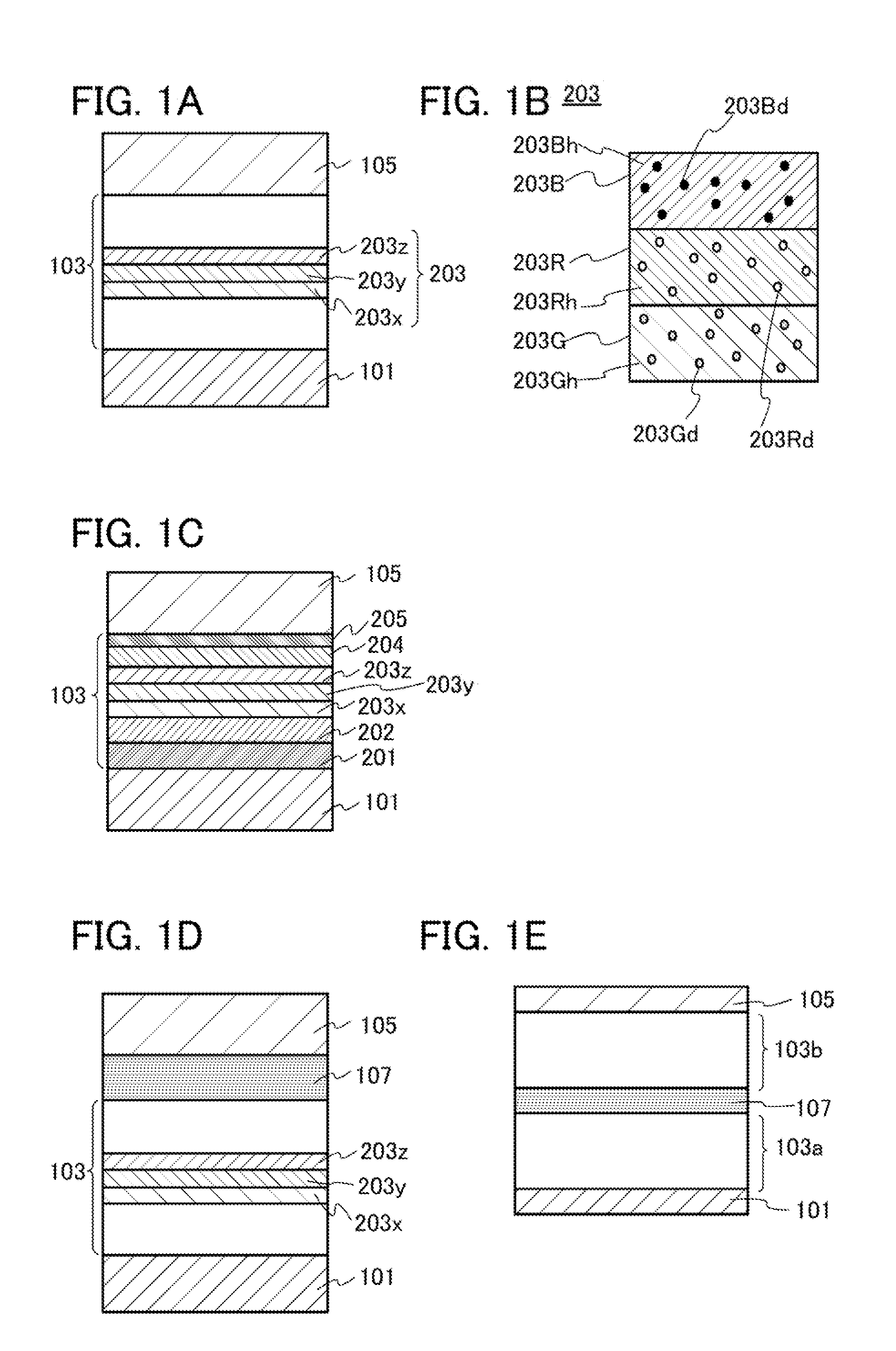
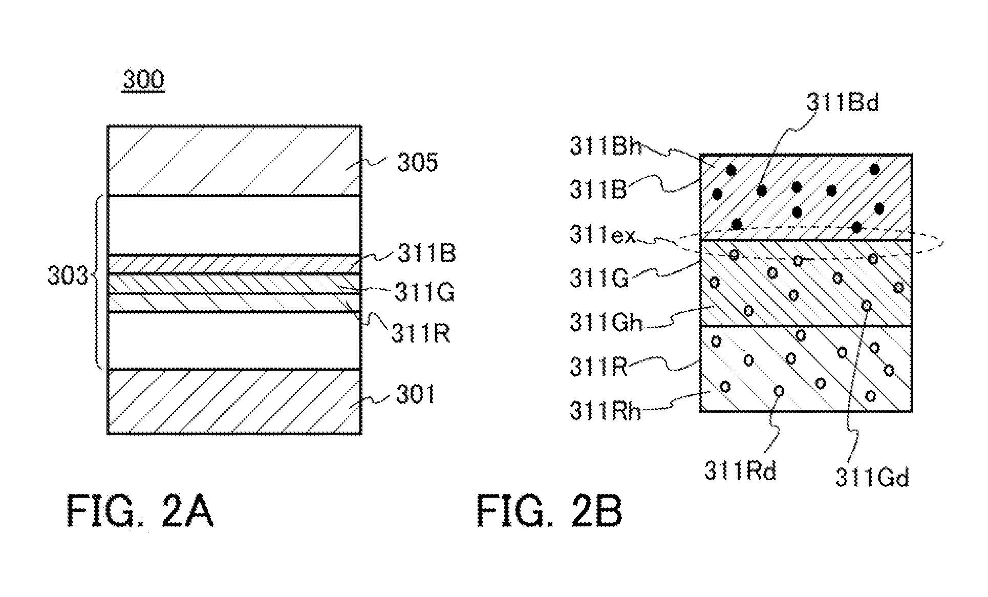
[0052]In this embodiment, light-emitting elements of embodiments of the present invention will be described with reference to FIGS. 1A to 1E, FIGS. 2A and 2B, and FIGS. 3A and 3B.

[0053]A point of one embodiment of the present invention is to use three kinds of phosphorescent compounds whose emission spectra have peaks at different wavelengths and to make all the three kinds of phosphorescent compounds emit light with high efficiency, thereby improving emission efficiency and a lifetime of a multicolor light-emitting element.

[0054]In a general method for obtaining a multicolor light-emitting element including a phosphorescent compound, a plurality of kinds of phosphorescent compounds whose emission spectra have peaks at different wavelengths are dispersed in some host material in an appropriate ratio. However, in such a method, the phosphorescent compound that emits light of the longest wavelength easily emits light, so that it is extremely difficult to design and control an element ...

embodiment 2

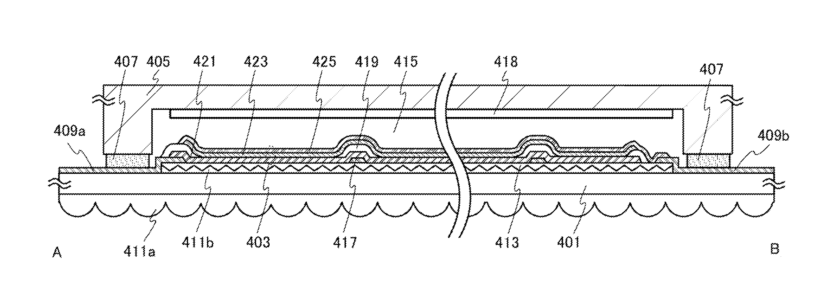
[0175]In this embodiment, a light-emitting device of one embodiment of the present invention will be described with reference to FIGS. 4A and 4B and FIGS. 5A and 5B. The light-emitting device in this embodiment includes the light-emitting element of one embodiment of the present invention. Since the light-emitting element has a long lifetime, a light-emitting device having high reliability can be provided.

[0176]FIG. 4A is a plan view of a light-emitting device of one embodiment of the present invention, and FIG. 4B is a cross-sectional view taken along dashed-dotted line A-B in FIG. 4A.

[0177]In the light-emitting device in this embodiment, a light-emitting element 403 is provided in a space 415 surrounded by a support substrate 401, a sealing substrate 405, and a sealing material 407. The light-emitting element 403 is a light-emitting element having a bottom-emission structure: specifically, a first electrode 421 which transmits visible light is provided over the support substrate 4...

embodiment 3

[0215]In this embodiment, examples of electronic devices and lighting devices to which the light-emitting device of one embodiment of the present invention is applied will be described with reference to FIGS. 6A to 6E and FIGS. 7A and 7B.

[0216]Electronic devices in this embodiment each include the light-emitting device of one embodiment of the present invention in a display portion. Lighting devices in this embodiment each include the light-emitting device of one embodiment of the present invention in a light-emitting portion (a lighting portion). Highly reliable electronic devices and highly reliable lighting devices can be provided by adopting the light-emitting device of one embodiment of the present invention.

[0217]Examples of electronic devices to which the light-emitting device is applied are television devices (also referred to as TV or television receivers), monitors for computers and the like, cameras such as digital cameras and digital video cameras, digital photo frames, ...


PUM


Abstract

A light-emitting element includes a first electrode; a first light-emitting layer over the first electrode, containing a first phosphorescent compound and a first host material; a second light-emitting layer over the first light-emitting layer, containing a second phosphorescent compound and a second host material; a third light-emitting layer over the second light-emitting layer, containing a third phosphorescent compound and a third host material; and a second electrode over the third light-emitting layer. Between peaks of emission spectra of the first, second, and third phosphorescent compounds, the peak of the emission spectrum of the second phosphorescent compound is on the longest wavelength side and that of the emission spectrum of the third phosphorescent compound is on the shortest wavelength side. The third host material has higher triplet excitation energy than the first host material and the second host material.

Description

BACKGROUND OF THE INVENTION[0001]1. Field of the Invention[0002]The present invention relates to a light-emitting element, a lighting device, a light-emitting device, and an electronic device. In particular, the present invention relates to a light-emitting element, a lighting device, a light-emitting device, and an electronic device utilizing electroluminescence (EL).[0003]2. Description of the Related Art[0004]Research and development have been extensively conducted on light-emitting elements utilizing EL. In a basic structure of the light-emitting element, a layer containing a light-emitting organic compound (hereinafter also referred to as an EL layer) is sandwiched between a pair of electrodes. The light-emitting element utilizing EL has attracted attention as a next-generation flat panel display element owing to characteristics such as feasibility of being thinner and lighter, high-speed response to input signals, and capability of direct current low voltage driving. In additi...

Claims


Application Information

Patent Timeline
IPC IPC(8): F21K99/00H05B44/00
CPCF21K9/50H10K85/633H10K85/654H10K85/6572H10K85/342H10K50/13H10K50/11H10K2101/10C09K11/06H10K85/615H10K85/626H10K85/636H10K85/6576H10K2101/40C07F15/0033C09K2211/1007C09K2211/1059C09K2211/185
Inventor ISHISONE, TAKAHIROSEO, SATOSHI
Owner SEMICON ENERGY LAB CO LTD
Why Eureka
Try Eureka