Adjustable golf putter head having teeth

a golf putter and adjustment technology, applied in the field of golf putters, can solve the problems of inability to uniformly distribute the dimples over the spherical surface of the ball, the assumption that the previous sentence is correct, and the inability to design a rotatable putter fa

Inactive Publication Date: 2017-12-21
BRANDT RICHARD A +1
View PDF3 Cites 3 Cited by
  • Summary
  • Abstract
  • Description
  • Claims
  • Application Information

AI Technical Summary

Benefits of technology

[0004]It is an object of the present invention to provide an improved gold putter head assembly.

Problems solved by technology

Previous attempts to design a rotatable putter face used impractical or ineffective mechanisms.
The problem is that none of the assumptions listed in the previous sentence are correct.(1) Essentially no golfer produces a club swing that causes the putter head to move in a perfectly horizontal direction as it strikes a ball.
It is, furthermore, impossible for these dimples to be uniformly distributed over the spherical surface of the ball.(3) Essentially no golf balls have uniform density.

Method used


Image

  • Adjustable golf putter head having teeth
  • Adjustable golf putter head having teeth
  • Adjustable golf putter head having teeth

Examples


Embodiment Construction

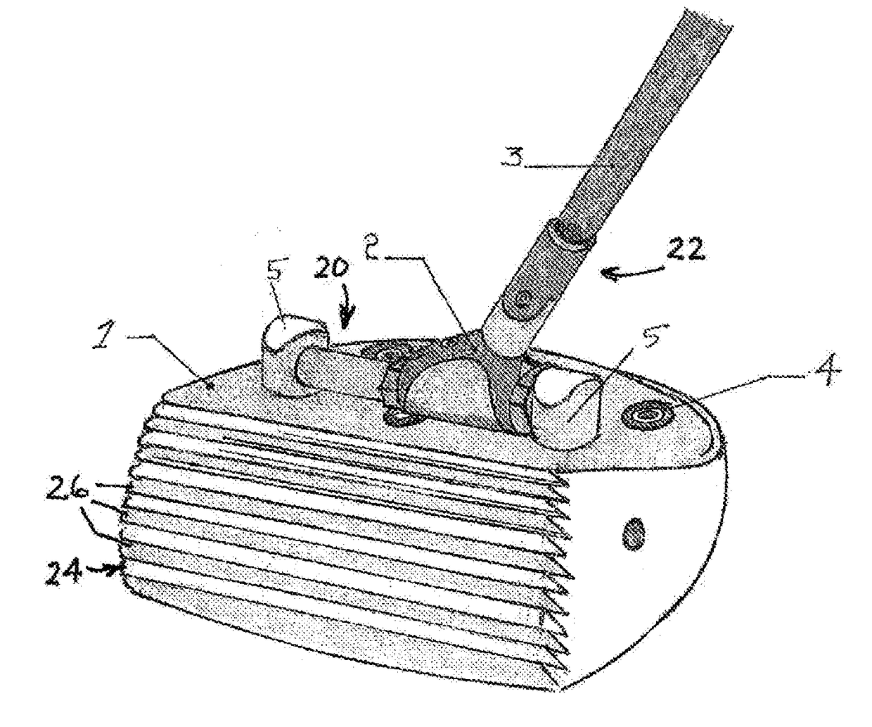
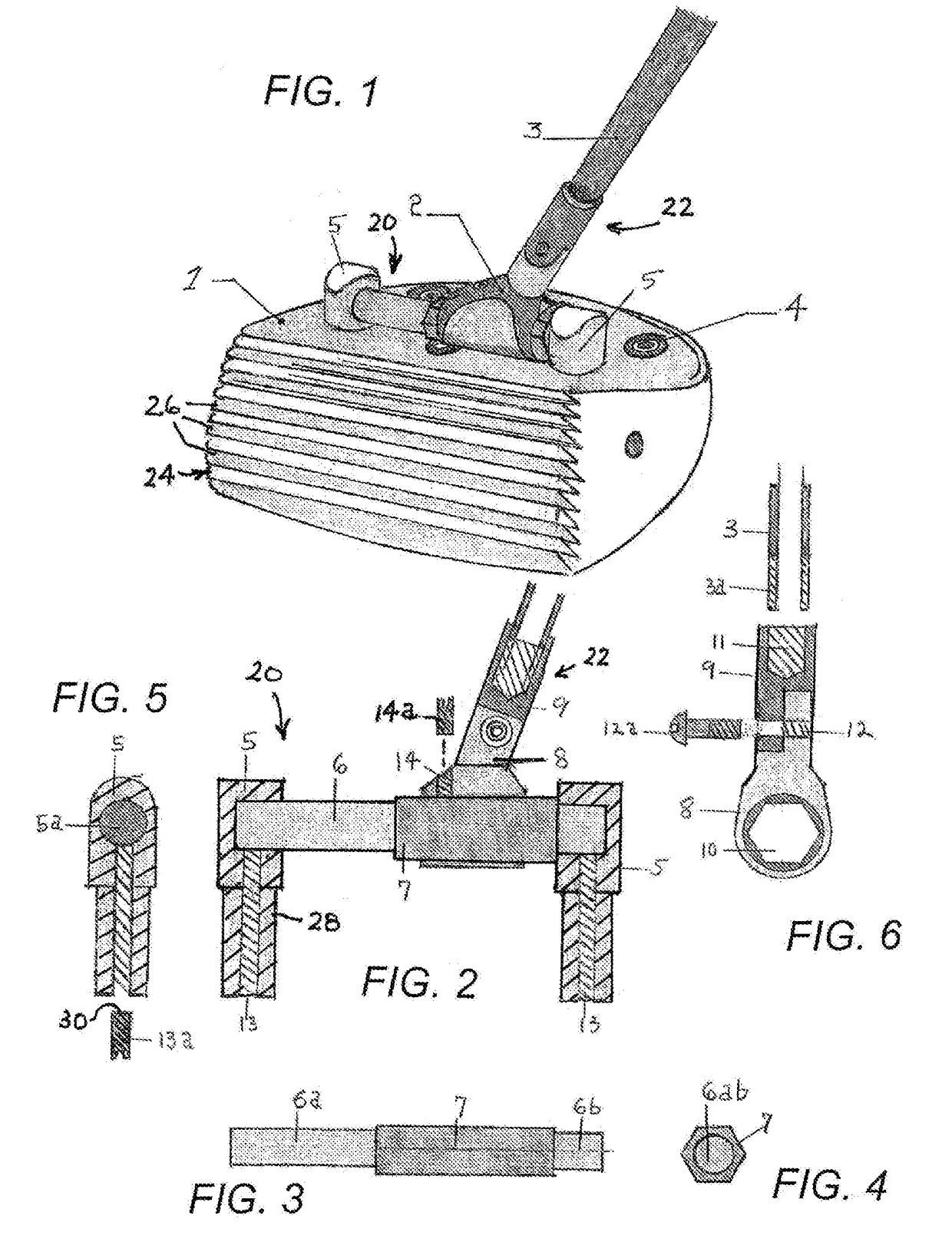
[0052]A preferred embodiment of a golf putter head assembly having a loft-angle adjustment mechanism is shown in FIG. 1. The assembly includes two parts, a putter head body 1 with an attached handle-like structure 20 on top, and a hosel component 22 connected thereto.

[0053]As shown in FIG. 6, hosel component 22 includes an upper section 9 and a lower section 8, adjustably fastened to one another via a bolt 12a, and further includes a slideable annulus-like member 2 that is attached to the bottom of the lower hosel section 8.

[0054]Handle-like attachment structure 20 includes a pair of handle supports or posts 5 which are vertically oriented cylindrical sections attached near the toe and the heel of the putter head body 1. Handle-like attachment structure 20 further includes a horizontally oriented rotatable solid cylindrical section or handle bar 6 lying above the top of the putter body 1, parallel to a front face 24 thereof, the bar 6 being inserted into supports or posts 5. Bar 6 h...


PUM


Abstract

In a golf club head assembly a body member has a top-forward angled front face, the face comprising a plurality of generally forward-facing teeth. The golf club head assembly further comprises a loft angle adjustment mechanism attached to the body member for adjusting a loft angle of the face. The mechanism includes a hosel element releasably attached to a bar rotatably mounted to an upper side of the body member parallel to the face. The bar is rotatably journaled or mounted in a pair of bar supports attached to the body member. Set screws reside in threaded holes in the bar supports, the set screws operable to releasably lock the bar in a selected orientation relative to the body member, where the selected orientation of the bar corresponds to and determines the loft angle of the front face. The forward angle of the front face, the angles of the teeth, and loft angle of the face are jointly chosen to impart a pure rolling motion onto a struck golf ball.

Description

BACKGROUND OF THE INVENTION[0001]This invention relates to a golf putter. More particularly, this invention relates to a golf putter head assembly that includes a mechanism for adjusting a loft angle of the front face of the putter head.[0002]When a conventional putter strikes a golf ball, the ball slides forward on the putting green with little or no spin. Because of the large (backwards directed) sliding friction between the ball and the green, this sliding motion is erratic and irregular, causing the ball's trajectory to deviate from its intended direction and speed. This frictional force does, however, cause the ball to both gain forward spin and lose forward speed at a continuously increasing rate. This process proceeds until pure rolling sets in when the point of contact between the ball and the green is instantaneously at rest. (The forward linear motion of the contact point is then exactly canceled by the backward rotational motion.). From this time on, the friction force be...

Claims


Application Information

Patent Timeline
Patent Type & Authority Applications(United States)
IPC IPC(8): A63B53/04A63B53/02
CPCA63B53/0487A63B53/02A63B2053/022A63B2053/0445A63B2053/026A63B53/022A63B53/023A63B53/025A63B53/0445
Inventor BRANDT, RICHARD A.SCEPANOVIC, DRAGOSLAV
Owner BRANDT RICHARD A
Why Eureka
Try Eureka