Eureka AIR delivers breakthrough ideas for toughest innovation challenges, trusted by R&D personnel around the world.

Pneumatic Tire

a technology of pneumatic tires and treads, applied in the field of pneumatic tires, can solve the problems of difficult to achieve excellent wear resistance performance, achieve good and reduce the rigidity of the land portion, so as to achieve improved snow performance and wear resistance performance.

Inactive Publication Date: 2017-12-21
YOKOHAMA RUBBER CO LTD
View PDF9 Cites 7 Cited by
  • Summary
  • Abstract
  • Description
  • Claims
  • Application Information

AI Technical Summary

Benefits of technology

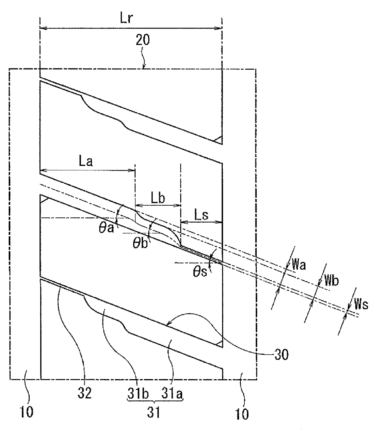
The present technology provides a pneumatic tire with improved snow performance and wear resistance performance. The compound grooves in the tire have a structure that maintains higher land portion rigidity and alleviates stress concentration, resulting in effective wear resistance performance. The groove width decreases in a stepped manner, and the plurality of lateral grooves formed in the same land portion do not all open toward the same side, which increases wear resistance performance. The ratios of groove widths in different portions of the compound groove are set to predetermined ranges to achieve good snow performance and wear resistance performance in a highly compatible manner. The groove walls on one side of the compound groove form a straight line, and the groove walls on the other side form a non-straight line that bends in a stepped manner, strengthening the improvement of wear resistance performance. The compound grooves adjacent in the tire circumferential direction are disposed so that either the groove walls that form straight lines or the groove walls that form non-straight lines face each other, improving rigidity and strengthening the improvement of wear resistance performance. A circumferential-direction auxiliary groove having a smaller width than the main grooves is provided to the land portions in which the compound grooves are formed, further improving snow performance.

Problems solved by technology

Nevertheless, when a large number of lateral grooves are provided, land portion rigidity decreases, making it difficult to achieve excellent wear resistance performance.
Nevertheless, simply adjusting the shape, the groove width, the disposition, and the like of the lateral grooves does not always achieve good snow performance and wear resistance performance in a highly compatible manner, and thus further improvement is required.

Method used


Image

  • Pneumatic Tire
  • Pneumatic Tire
  • Pneumatic Tire

Examples


examples

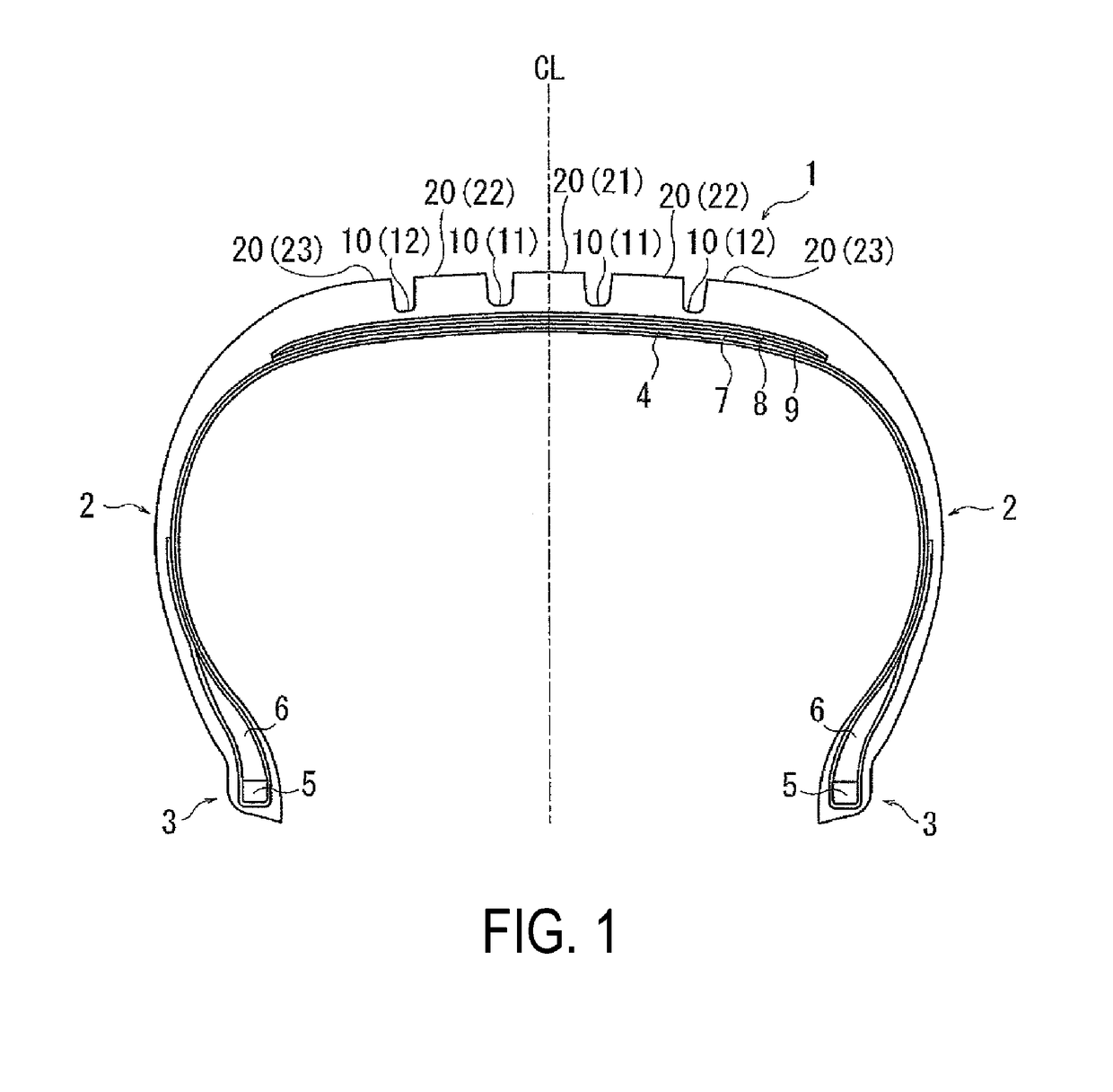
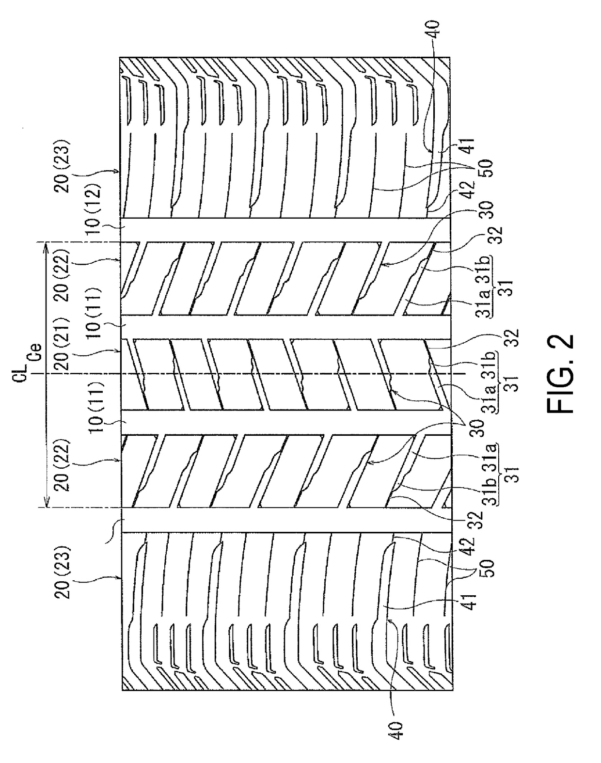
[0049]As Conventional Example 1, Comparative Examples 1 to 3, and Examples 1 to 11, 15 types of pneumatic tires were produced using tires having a tire size of 215 / 60R16, the reinforcement structure illustrated in FIG. 1, and the tread pattern illustrated in FIG. 2 excluding the compound grooves (and the circumferential-direction auxiliary grooves), as bases. The structure of the compound grooves, the groove width ratios (ratio Wa / Wb and ratio Wb / Ws) of the compound grooves, the groove length ratios (ratio La / Lr, ratio Lb / Lr, and ratio Ls / Lr), the presence / absence of the circumferential narrow grooves, and the groove width of the circumferential narrow grooves were set as indicated in Table 1.

[0050]In these 15 types of pneumatic tires, the shape of the compound groove is common to that illustrated in FIG. 3, except for Conventional Example 1, Comparative Examples 1 and 2, and Example 4. That is, each of the compound grooves includes a lateral groove having a first end that communica...


PUM


Abstract

Provided is a pneumatic tire having plurality of compound grooves, each including a lateral groove having a first end that communicates with a main groove on one side thereof and a second end that terminates inside a land portion, and further including a sipe that extends from the second end of the lateral groove to the main groove on the other side thereof, are formed at an interval in a tire circumferential direction in at least one row of the land portions positioned inside a center region. The compound grooves are disposed so that an opening direction of the lateral grooves relative to the main grooves alternatingly reverses in the tire circumferential direction. The lateral grooves each include a broad width portion and a narrow width portion.

Description

TECHNICAL FIELD[0001]The present technology relates to a pneumatic tire and particularly relates to a pneumatic tire with improved snow performance and wear resistance performance.BACKGROUND ART[0002]All-season pneumatic tires that are presumably used throughout the year on dry road surfaces, wet road surfaces, snow-covered road surfaces, and the like require regular dry performance and wet performance as well as snow performance (steering stability performance on snow-covered road surfaces, for example). Additionally, because such pneumatic tires can be used on various road surfaces as described above, the tires require wear resistance performance for long-term use.[0003]Examples of possible methods for improving snow performance include providing a large number of lateral grooves that extend in the tire width direction to secure edge components. Nevertheless, when a large number of lateral grooves are provided, land portion rigidity decreases, making it difficult to achieve excell...

Claims


Application Information

Patent Timeline
IPC IPC(8): B60C11/03B60C11/12
CPCB60C11/0309B60C2011/0365B60C11/1236B60C11/03B60C11/12B60C2011/1209B60C2011/0372
Inventor YAMAKAWA, TAKAHIRO
Owner YOKOHAMA RUBBER CO LTD
Why Eureka
Eureka Blog
Learn More