Anchor chain

a technology of anchor chain and chain, which is applied in the direction of hoisting chain, shackle, and chain, can solve the problems of deformation of the contact area between the links, bending the elastic limit of the material of the links, and creating flats at the interfaces between adjacent links, so as to avoid bending fatigue in the links

Active Publication Date: 2017-12-21
IDEOL
View PDF0 Cites 0 Cited by
  • Summary
  • Abstract
  • Description
  • Claims
  • Application Information

AI Technical Summary

Benefits of technology

[0009]The present invention seeks to remedy those drawbacks. More specifically, the present description seeks to propose an anchor chain that makes it possible to avoid bending fatigue in links at the end of the chain.
[0012]Because of the increase in the bar diameter and / or the elastic limit in the material of at least three successive links at the end of the cable, it is possible to limit the formation of flats, and thus the transmission of bending moments, between these at least three links that are the most exposed to lateral forces.
[0014]Furthermore, by spreading out forces during the strength tests, this increase in diameter limits local plastic deformation of links during strength tests, thereby reducing the formation of flats. Furthermore, for a given bending moment, the bending stress is inversely proportional to the cube of this diameter. Consequently, even if the lever arm, and thus the bending moment, increases in a manner that is directly proportional to said diameter of the link, for a given lateral force, the stress will reduce with the square of the diameter. As a result of these two effects in combination, increasing the diameter of the links in the second plurality thus makes it possible to reduce the bending stresses at the head end of the chain very significantly whenever the anchor chain is subjected to lateral forces by pivoting movements of the floating body.
[0016]This increase in the elastic limit reduces the area of each link of said second plurality that is subjected to plastic deformation during strength testing, and thus also serves to reduce the formation of flats that facilitate the transmission of bending moments between adjacent links.

Problems solved by technology

It has been discovered that strength tests performed on chains before they are installed constitute a significant source of such geometrical imperfections.
Typically, during such tests, chains are tested up to 70% of their breaking load, which can nevertheless cause the elastic limit of the material of the links to be exceeded at certain points, thereby permanently deforming the areas of contact between links and creating flats at the interfaces between adjacent links.

Method used


Image

  • Anchor chain
  • Anchor chain
  • Anchor chain

Examples


Embodiment Construction

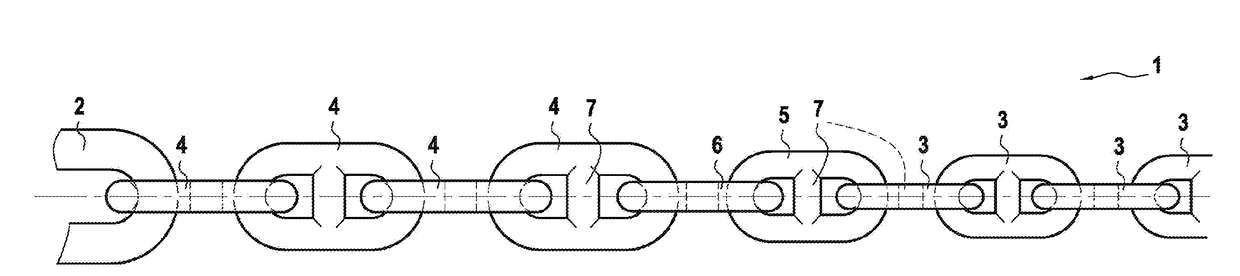
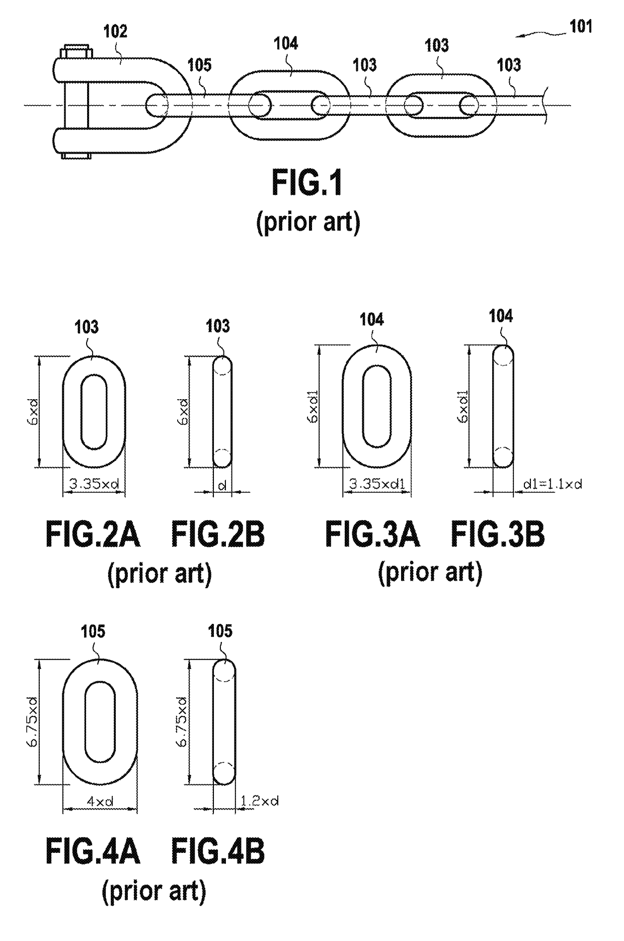
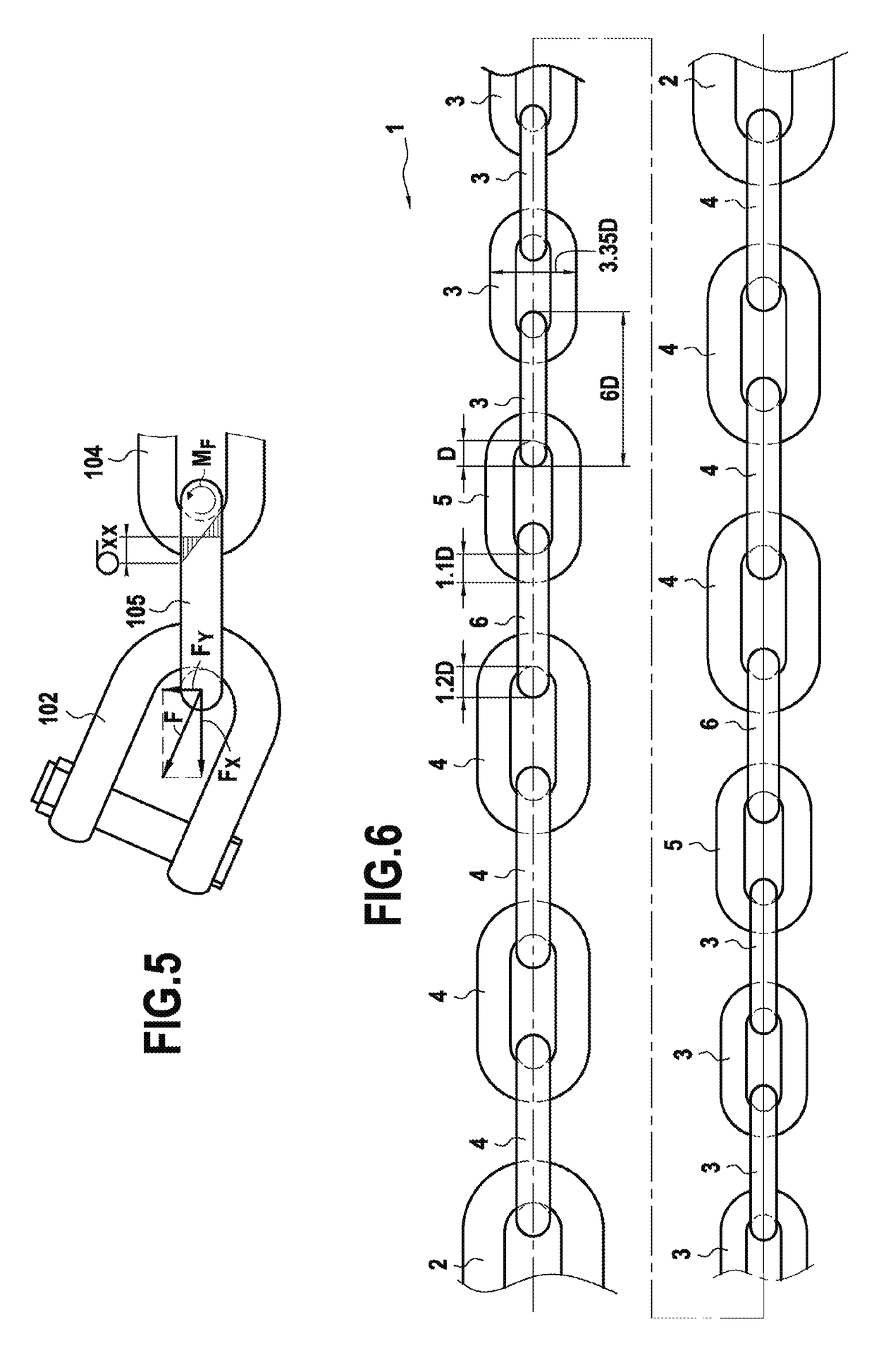
[0032]FIG. 1 shows a prior art anchor chain 101 in compliance with the API Spec 2F standard of the American Petroleum Institute. This anchor chain 101, which is connected at one end to an anchor shackle 102, comprises a plurality of successive common links 103, and between these common links 103 and the shackle 102, a standard enlarged link 104, and an end link 105.

[0033]As shown in FIGS. 2A and 2B, each common link 103 presents a bar diameter d, a width equal to 3.35 times d, and a length equal to six times d. The standard enlarged link 104, which in the chain 101 is adjacent to said plurality of successive common links 103, and which is shown in detail in FIGS. 3A and 3B, presents a bar diameter d1 equal to 1.1 times the bar diameter d of the common links 103, a width equal to 3.35 times d1, and a length equal to six times d1. Finally, the end link 105, which is interposed between the standard enlarged link 104 and the anchor shackle 102, resents a bar diameter equal to 1.2 times ...


PUM


Abstract

The invention relates to the field of anchor chains, and more particularly an anchor chain (1) comprising a first plurality of links (3) and, at the end of the chain, a second plurality of links (4) comprising at least three successive links (4) in each of which at least one property selected from its bar diameter and the elastic limit of its material is substantially greater than in each of the links (3) of the first plurality, in order to improve the ability of the chain to withstand fatigue by bending of the links (4) in the second plurality.

Description

BACKGROUND OF THE INVENTION[0001]The present invention relates to the field of anchor chains, and more particularly to anchor chains for applications at sea.[0002]In the present context, the term “anchor chain” is used to mean a succession of links connected to one another for transmitting mechanical tension, and serving in particular to connect a floating body to an anchor point in order to restrict the movement of said floating body. The links of such an anchor chain may in particular be made of metal. They may be stud links, in order to avoid them being flattened, or they may be links without studs.[0003]Although anchor chains are designed to transmit mechanical forces mainly in tension, in practice, chains anchoring a floating body and subjected to high levels of tension can also be subjected, at their ends, to large bending stresses, in particular in the proximity of their connection with the floating body. The cause of this bending is the combination of pivoting movements of t...

Claims


Application Information

Patent Timeline
Patent Type & Authority Applications(United States)
IPC IPC(8): F16G15/12F16G13/12B63B21/20
CPCF16G15/12F16G13/12B63B21/20B63B21/50B63B2035/446B63B2209/20F16G13/14F16G13/16F16G15/00F16G15/04
Inventor CHOISNET, THOMASMAROBIN, STEPHAN
Owner IDEOL
Why Eureka
Try Eureka