Toroidal continuously variable transmission

a technology of continuous variable transmission and toroidal, which is applied in the direction of transportation and packaging, other domestic objects, and gearing, etc., can solve the problems of reducing the production cost of the traction surface corresponding to the surface to be processed, reducing the cost of processing devices, and reducing the cost of forming the concave groov

Active Publication Date: 2015-11-17
NSK LTD
View PDF14 Cites 0 Cited by
  • Summary
  • Abstract
  • Description
  • Claims
  • Application Information

AI Technical Summary

Benefits of technology

[0022]The present invention is contrived in consideration of the above-described problems, and one of objects of the invention is to provide a structure in which a plurality of concave grooves (fine grooves) are formed in both a peripheral surface of a power roller and a one-side surface of a disk in an axial direction in order to improve a traction coefficient of a rolling contact area between the axially one-side surface and the peripheral surface of the power roller while ensuring durability of the disk and the power roller. Further, the present invention also relates to provide a construction for achieving the plurality of the concave grooves with low cost and relates to a manufacturing method of the plurality of concave grooves with low cost.
[0050]According to the toroidal continuously variable transmission described above, it is possible to provide the structure provided with a plurality of concave grooves improving a traction coefficient while ensuring durability of the disk and the power roller.
[0051]That is, since the concave grooves are formed in both the axially one-side surface and the peripheral surface of the power roller (both traction surfaces), it is possible to ensure a sufficient traction coefficient even when the depth of the concave grooves is small (is not extremely deep). Accordingly, it is possible to easily ensure durability of the working tool for forming the concave grooves, and thus it is possible to reduce a manufacture cost. In addition, when the concave grooves are formed by a rolling process, it is possible to prevent the processed surface where the concave grooves are formed from being broken, and to prevent bending fatigue from deteriorating.
[0052]In addition, as described above, the power roller-side concave grooves formed in the peripheral surface of the power roller are opposed to the disk-side concave grooves formed in the axially one-side surface in the rolling contact area (traction area) between the peripheral surface of the power roller and the axially one-side surface regardless of the transmission gear ratio between the disks. Accordingly, for instance, a problem that a substantial contact area of the rolling contact area (a total sum of a contact area in the rolling contact area other the concave grooves) becomes small at a certain transmission gear ratio does not occur. Accordingly, it is possible to prevent an excessive large surface pressure or a metal contact in the rolling contact area occurring upon operating the apparatus in a state that the contact area is extremely small, and thus it is possible to ensure durability of the disk and the power roller.
[0055]When arranging the concave grooves as described above, it is possible to form the concave grooves at low cost. The reason is because the concave grooves can be formed by rotating the member where the concave grooves need to be formed at a constant speed while displacing (swinging) the working tool at a constant speed in the diameter direction (and in the axial direction) of the member where the concave grooves need to be formed in a state that the working tool (a groove forming cutting tool such as a precision-work bite or a grinding tool such as a super-finishing grindstone) for forming the concave grooves are brought into direct contact with the surface to be processed. In addition, the reason why the concave grooves can be formed by rotating the disk at a constant speed while displacing the working tool at a constant speed that a circumferential speed of the part processed by the working tool changes such that a circumferential speed on the outer diameter side is faster than that on the inner diameter side. Accordingly, an angle with respect to the circumferential direction becomes small as much as the circumferential speed is fast.
[0056]For this reason, since it is not necessary to change a rotation speed of the member where the concave grooves need to be formed or to change a displacement speed of the working tool upon processing the concave grooves, it is not necessary to provide a mechanism for changing a rotation speed to the processing device. In addition, since it is possible to reduce a cost of the processing device as much as a cost of the mechanism which is not provided thereto, it is possible to reduce a cost for forming the concave grooves.

Problems solved by technology

However, when applying such a large pressing force, durability of the input-side and output-side disks 1 and 6 or the power rollers 8 and 8 may deteriorate.
However, when the depth of the concave grooves is set to large (deep), it is difficult to ensure durability of a working tool for forming the concave grooves, and thus a manufacture cost may increase.
In addition, when the concave grooves are formed by, for instance, a rolling process, a traction surface corresponding to the surface to be processed may be broken or bending fatigue thereof may deteriorate.
Then, in such a state, when the contact area in the rolling contact area becomes small, durability of the disks 1 and 5 or the power rollers 8 and 8 may deteriorate, which is not desirable.

Method used


Image

  • Toroidal continuously variable transmission
  • Toroidal continuously variable transmission
  • Toroidal continuously variable transmission

Examples


first embodiment

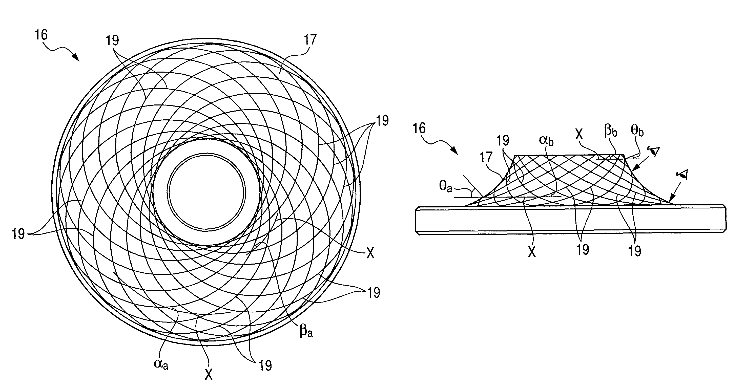
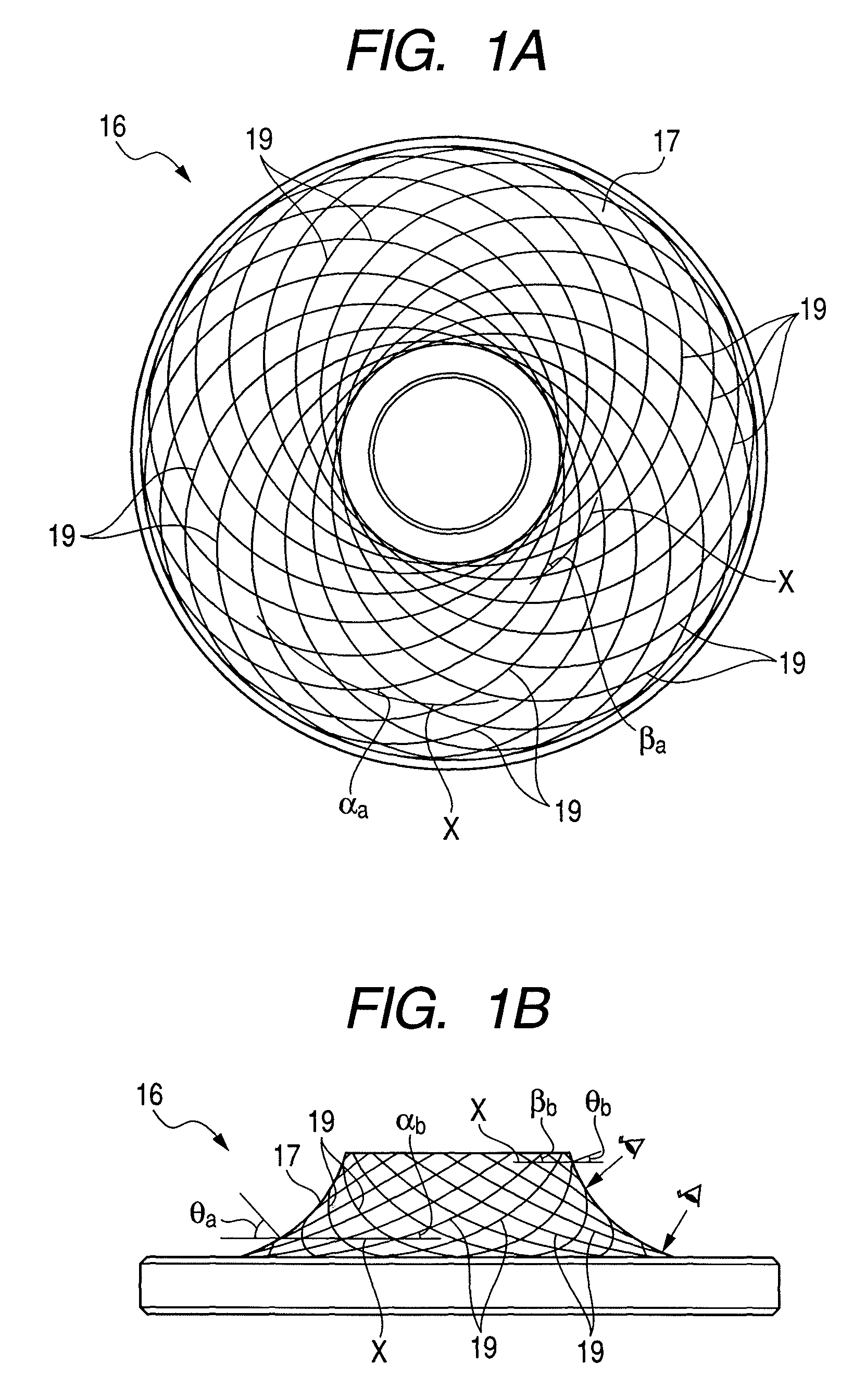
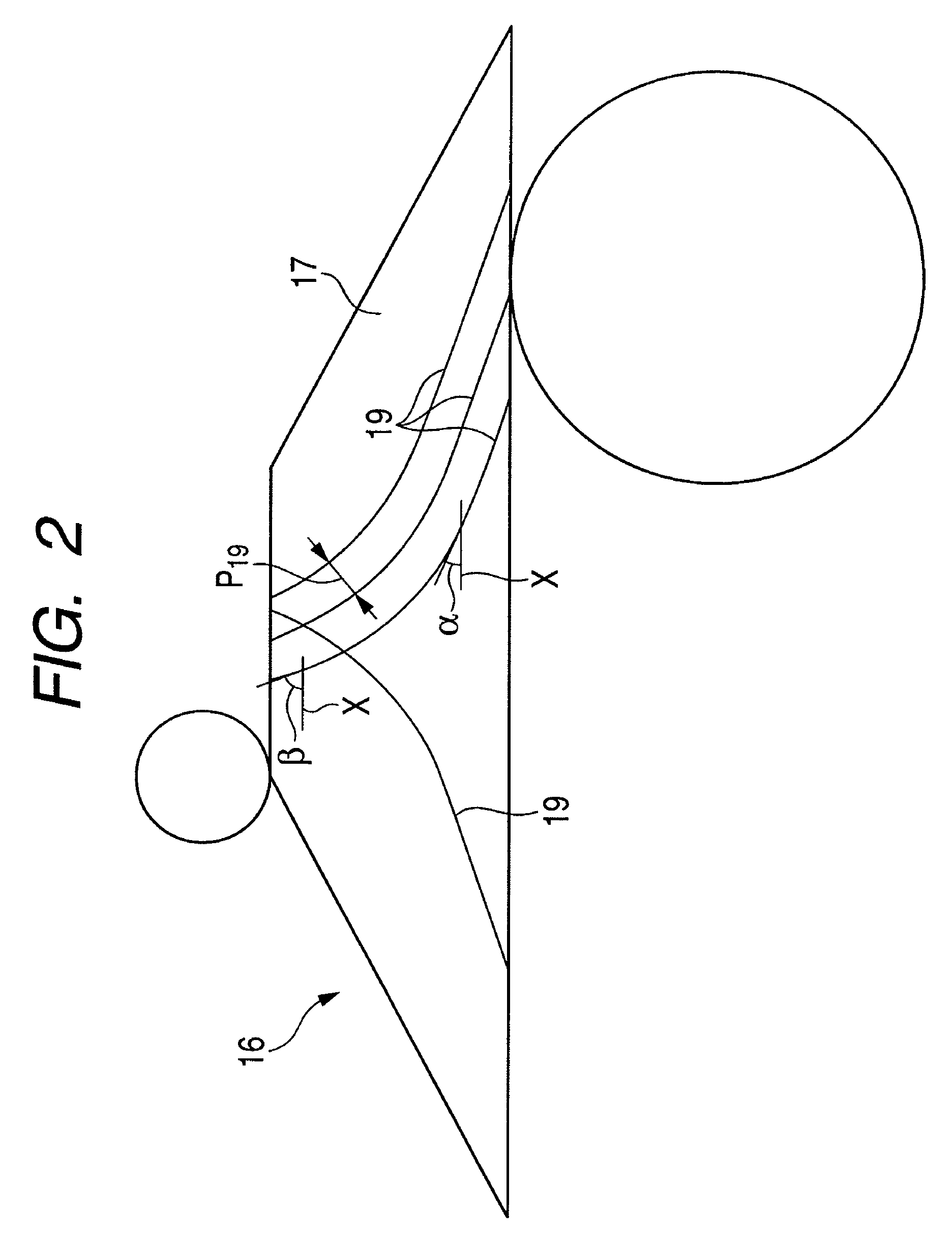
[0079]FIGS. 1 to 3 show a first embodiment of the invention. In addition, a characteristic of this embodiment is to study a principle of concave grooves 19, 20 in order to provide a structure with a plurality of concave grooves 19, 20 improving a traction coefficient while ensuring durability of a disk 16 (which corresponds to an input-side disk 1 and an output-side disk 6 shown in FIG. 9) and a power roller 8. Since the other structures and effects are the same as those of the known example described in FIGS. 9 and 10, the repetitive drawings and descriptions thereof will be omitted or described in brief. Hereinafter, a characteristic part of this embodiment will be mainly described.

[0080]In this embodiment, as shown in FIGS. 1 and 2, a plurality of concave grooves 19, 19 are formed in a whole one-side surface 17 (which corresponds to a surface shown in FIGS. 1A and 2, an upper surface shown in FIG. 1B, an input-side inner surface 3, and an output-side inner surface 7 shown in FIG....

second embodiment

[0102]FIGS. 4 and 5 show a second embodiment of the invention. In this embodiment, as shown in FIG. 4, the disk-side concave grooves 19, 19 are formed into a concentric shape (or a spiral shape) about the central shaft (rotation shaft) of the disk 16. Meanwhile, as shown in FIG. 5, the power roller-side concave grooves 20, 20 are formed so as to have angles with respect to the circumferential direction of the power roller 8 when viewed from a normal direction relative to the peripheral surface 18 of the power roller 8. Then, in this embodiment, the angles are formed such that an angle on the inner diameter side of the power roller 8 is larger than that on the outer diameter side thereof.

[0103]The other configurations, effects, and methods of forming the power roller-side concave grooves 20, 20 are the same as those of the first embodiment described above except that the concave grooves having the angles are the power roller-side concave grooves 20, 20 and the surface (the peripheral...

third embodiment

[0104]FIGS. 6 to 8 show a third embodiment. In this embodiment, in the same way as the second embodiment described above, the disk-side concave grooves 19, 19 are formed into a concentric shape (or a spiral shape) about the central shaft (rotation shaft) of disks 16a and 16b. However, in this embodiment, the disk-side concave grooves 19, 19 are formed only in a part where the peripheral surface 18 of the power roller 8 comes into rolling contact with the one-side surface 17 of the disks 16a and 16b in the axial direction in a state of a transmission gear ratio particularly necessary to ensure a traction coefficient (the disk-side concave grooves 19, 19 are not formed on the whole one-side surface 17). Specifically, as described in FIG. 9, when the transmission gear ratio between the input-side disks 1 and 1 and the output-side disks 6 and 6 is in a deceleration state, the disk-side concave grooves 19, 19 are formed only in a part where the peripheral surface 18 of the power roller 8...


PUM

PropertyMeasurementUnit
anglesaaaaaaaaaa
anglesaaaaaaaaaa
depthaaaaaaaaaa

Abstract

Power roller-side concave grooves are opposed to disk-side concave grooves 19, 19 so as to have angles therebetween in a rolling contact area between a peripheral surface of the power roller and a one-side surface 17 of a disk 16 in an axial direction regardless of a transmission gear ratio of a toroidal continuously variable transmission. Accordingly, the disk-side concave grooves 19, 19 are formed so as to have angles with respect to a circumferential direction of the disk 16 when viewed from a normal direction relative to the one-side surface 17 in the axial direction. Meanwhile, the power roller-side concave grooves are formed into a concentric shape (or a spiral shape) about a central shaft of the power roller. As a result, it is possible to prevent a decrease of a contact area in the rolling contact area regardless of the transmission gear ratio.

Description

BACKGROUND OF THE INVENTION[0001]1. Field of the Invention[0002]The present invention relates to an improvement of a toroidal continuously variable transmission which is used as a transmission unit constituting an automatic transmission apparatus for a vehicle or as a transmission for adjusting the operation speeds of various kinds of industrial machines such as a pump. Specifically, the present invention provides a structure in which a plurality of concave grooves (fine grooves) are formed in both a peripheral of a power roller and a one-side surface of a disk in an axial direction in order to improve a traction coefficient of a rolling contact area between the axially one-side surface and the peripheral surface of the power roller while ensuring durability of the disk and the power roller. Further, the present invention provides such the concave grooves with low cost.[0003]2. Description of Related Art[0004]In some field, a toroidal continuously variable transmission is generally ...

Claims


Application Information

Patent Timeline
Patent Type & Authority Patents(United States)
IPC IPC(8): F16H15/38
CPCF16H15/38Y10T29/49464
Inventor NISHII, HIROKIIMANISHI, TAKASHI
Owner NSK LTD
Why Eureka
Try Eureka