Composite Hard-Surface Material and Preparation Method Therefor
Active Publication Date: 2017-12-28
SEED TECH CORP LTD
View PDF0 Cites 2 Cited by
Summary
Abstract
Description
Claims
Application Information
AI Technical Summary
This helps you quickly interpret patents by identifying the three key elements:
Problems solved by technology
Method used
Benefits of technology
Benefits of technology
The present invention provides a composite hard-face material and a method for preparing it. The composite hard-face material has good abrasion resistance. The method involves dispersing hard-alloy sheets on the surface of a metal matrix, resulting in a composite hard-face material that exhibits excellent abrasion resistance. The solder used in the process contains nickel-based alloy powder, tungsten carbide particles, and boron nitride powder. These materials provide good flowability, high hardness, and good weldability, improving the abrasion resistance of the composite hard-face material.
Problems solved by technology
However, for some extremely harsh working conditions or some parts that require high abrasion and corrosion resistance properties or the like, such as TC bearings, drilling tools, stabilizers, etc., they are often operated in a liquid medium that is high erosional, strong acidic, strong alkali or the like and are susceptive to erosion and abrasion, thus the above hard-face materials cannot satisfy their use requirements.
However, the matrix of the composite hard-face material prepared by means of sintering has a decreased hardness due to a high sintering temperature, thus the resultant products are easy to deform during use, affecting the cooperated use between respective parts.
For the composite hard-face material prepared by means of spray welding, the bonding between the hard face layer and the matrix is not strong enough due to a semi-metallurgical bonding, and the hard face layer tends to peel off from the products during use.
Moreover, the material prepared by means of spray welding has 2% to 5% of microporosity, which will greatly reduce the abrasion resistance of the hard face layer.
Method used
Image
Click on the blue label to locate the original text in one second.
Reading with bidirectional positioning of images and text.
Examples
example 1
[0076]A steel mesh having a thickness of 0.2 mm and a mesh size of 1 mm was covered on the excircle surface of a cylindrical 42CrMo matrix having a size of mm×190 mm×50 mm, and then bent such that it could completely cover the excircle surface of the 42CrMo matrix.
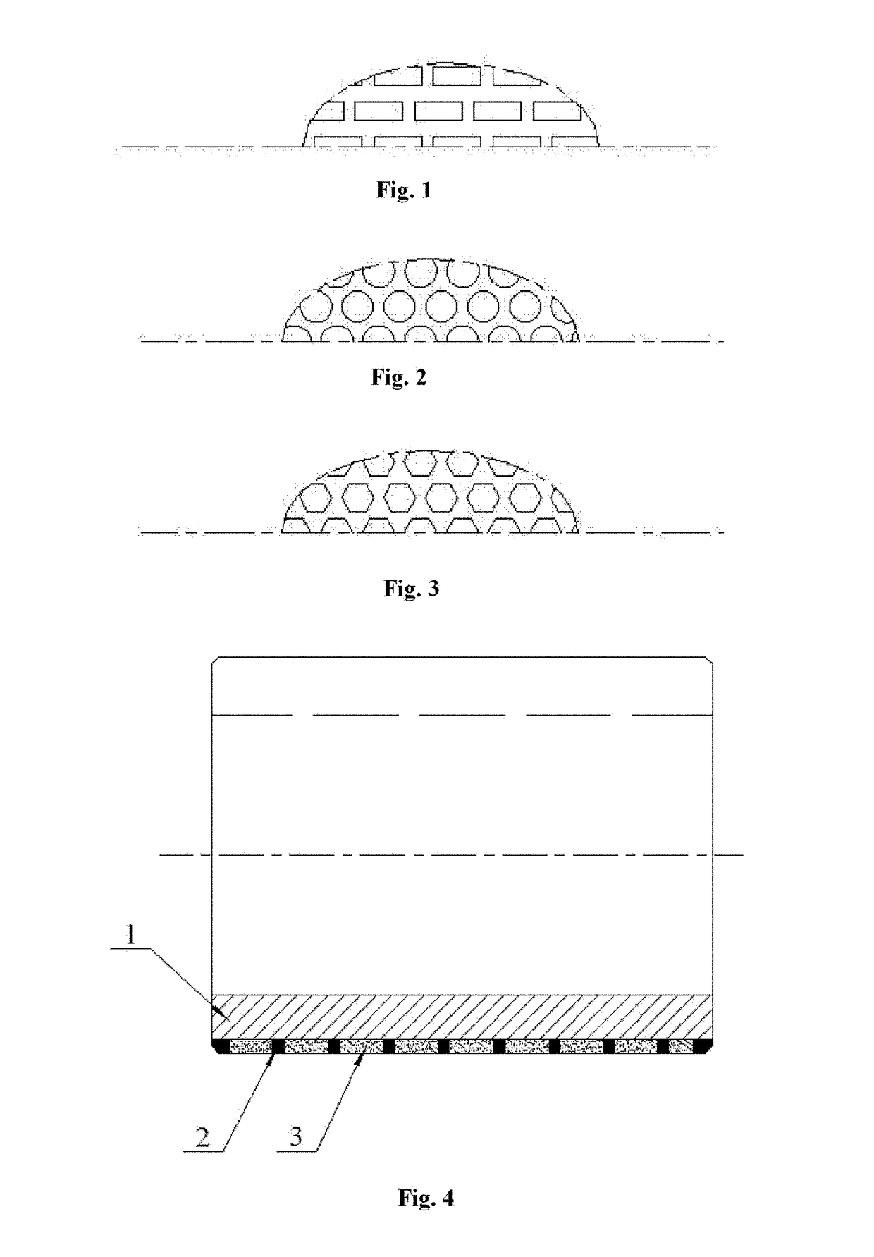
[0077]A mold made of asbestos paper material and having a thickness of 1.5 mm was placed on the surface of the steel mesh in which the shape and arrangement of holes in the mold was as shown in FIG. 1, and the holes in the mold had a length of 13 mm and a width of 5 mm, and then bent to allow its shape to conform to the excircle surface of the 42CrMo matrix.
[0078]0.1 mm thick red copper sheets were disposed in each hole in the mold, and 3 mm thick YG10-type rectangular hard-alloy sheets of 13 mm×5 mm (provided by Zhuzhou Sidi Hard Alloy Technology Co., Ltd.) were placed on each red copper sheet, wherein the coverage of the hard-alloy sheets on the excircle surface of the 42CrMo matrix was 45%.
[0085]A steel mesh having a thickness of 0.2 mm and a mesh size of 1 mm was covered on the inner hole surface of a cylindrical 42CrMo matrix having a size of Φ120 mm×190 mm×50 mm, and then bent such that it could completely cover the inner hole surface of the 42CrMo matrix.
[0086]A mold made of asbestos paper material and having a thickness of 1.5 mm was placed on the surface of the steel mesh in which the shape and arrangement of holes in the mold was as shown in FIG. 1, and the holes in the mold had a length of 13 mm and a width of 5 mm, and then bent to allow its shape to conform to the inner hole surface of the 42CrMo matrix.
[0087]0.1 mm thick red copper sheets were disposed in each hole in the mold, and 5 mm thick hard-alloy sheets of YG10 type hard-alloy sheets (provided by Zhuzhou Sidi Hard Alloy Technology Co., Ltd.) were placed on each red copper sheet, wherein the cross section of the hard-alloy sheet was a rectangular shape, the longitudinal section of the hard alloy sheet...
example 3
[0094]A steel mesh having a thickness of 0.2 mm and a mesh size of 1 mm was covered on the upper surface (annular plane) of a cylindrical 42CrMo matrix having a size of Φ120 mm×190 mm×50 mm, wherein the annular steel mesh could completely cover the upper surface of the 42CrMo matrix.
[0095]An annular mold made of asbestos paper material and having a thickness of 1.5 mm was placed on the surface of the steel mesh in which the shape and arrangement of holes in the mold was as shown in FIG. 1, and the holes in the mold had a length of 13 mm and a width of 5 mm, wherein the shape of the annular mold conformed to the upper surface of the 42CrMo matrix.
[0096]0.1 mm thick red copper sheets were disposed in each hole in the mold, and 5 mm thick YG10-type rectangular hard-alloy sheets of 13 mm×5 mm (provided by Zhuzhou Sidi Hard Alloy Technology Co., Ltd.) were placed on each red copper sheet, wherein the coverage of the hard-alloy sheets on the upper surface of the 42CrMo matrix was 58%.
[009...
PUM
Abstract
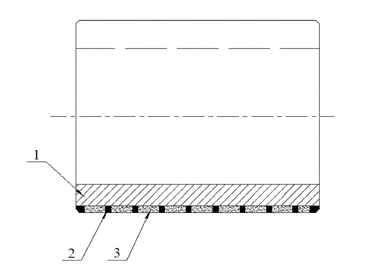
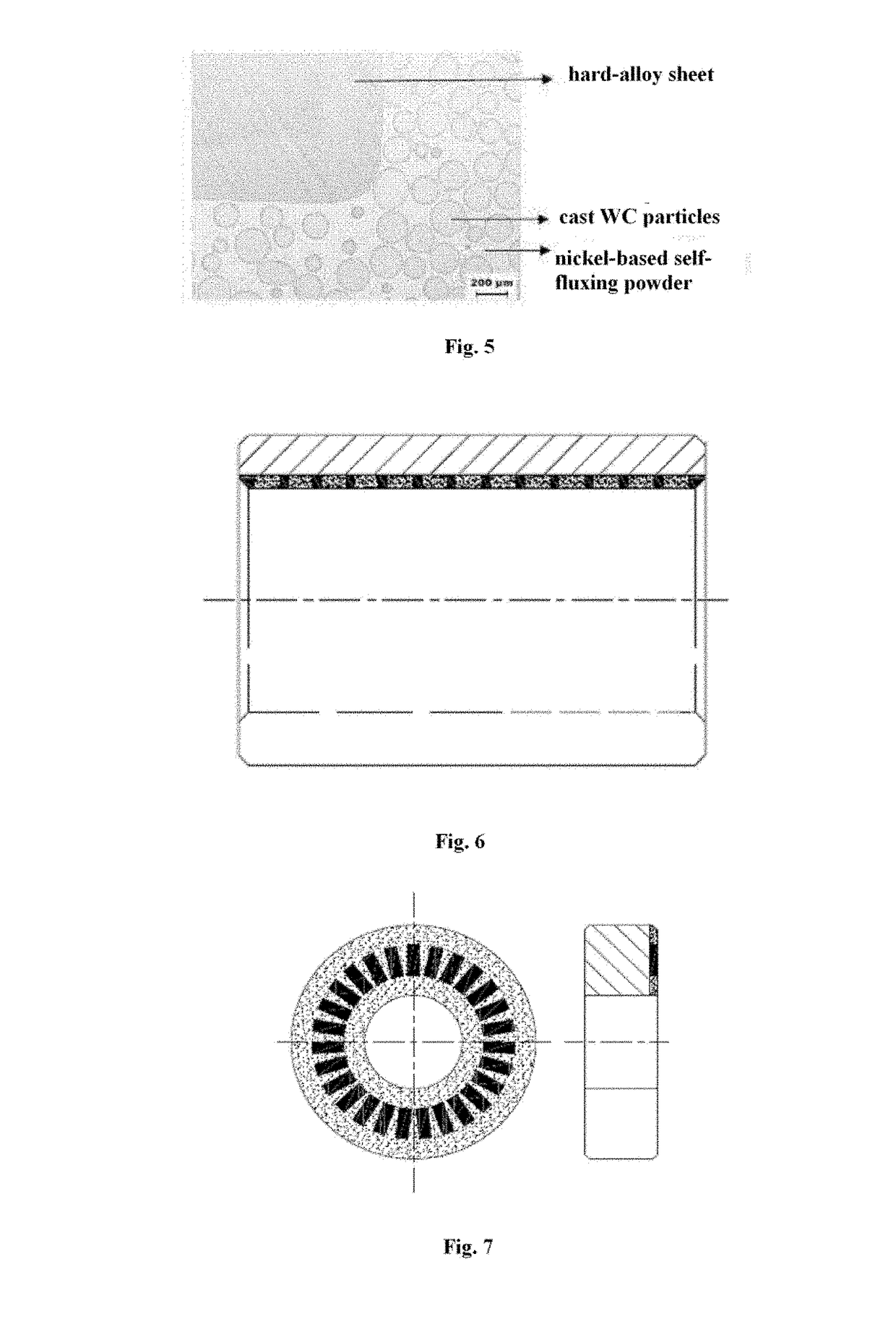
A composite hard-surface material preparation method and a composite hard-surface material prepared thereby, the preparation method comprising: dispersedly fixing a plurality of cemented carbide sheets (2) to a surface of a metal substrate (1); and surfacing the cemented carbide sheets (2) and the metal substrate (1) with a solder (3) to obtain a composite hard-surface material, the solder (3) comprising nickel-based alloypowder, tungstencarbide particles and boronnitridepowder. The solder (3) used in the preparation of the composite hard-surface material comprises nickel-based alloypowder, tungstencarbide particles and boronnitride powder, wherein the nickel-based alloy powder can increase fluidity and corrosion resistance, the tungstencarbide particle can improve hardness, and the boronnitride powder can effectively reduce friction coefficient. The present solder has good fluidity, high hardness and good solderability, using said solder, the obtained composite hard-surface material may enjoy good wear resistance.
Description
[0001]The present application claims the priority of Chinese Patent Application No. 201510816202.8, filed with the Chinese Patent Office on Nov. 20, 2015 and entitled “Composite hard-face material and method for preparing the same”, the entire disclosure of which is incorporated herein by reference.FIELD OF THE INVENTION[0002]The present invention relates to the technical field of hard-face material, and in particular to a composite hard-face material and a method for preparing the same.BACKGROUND OF THE INVENTION[0003]Hard-face technology is a metal surface reinforcement technology, and comprises thermal spraying, spray welding, overlaywelding, and the like. The essence of hard-face technology lies in using composite material to prepare metal mechanical parts such that the metal mechanical parts have good abrasion resistance, corrosion resistance, and high-temperature resistance. A wide variety of products can be produced by hard-face technology, and can be widely used in iron and...
Claims
Application Information
Patent Timeline
Application Date:The date an application was filed.
Publication Date:The date a patent or application was officially published.
First Publication Date:The earliest publication date of a patent with the same application number.
Issue Date:Publication date of the patent grant document.
PCT Entry Date:The Entry date of PCT National Phase.
Estimated Expiry Date:The statutory expiry date of a patent right according to the Patent Law, and it is the longest term of protection that the patent right can achieve without the termination of the patent right due to other reasons(Term extension factor has been taken into account ).
Invalid Date:Actual expiry date is based on effective date or publication date of legal transaction data of invalid patent.

