Cutting insert, cutting tool, and method for manufacturing machined product

a cutting tool and insert technology, applied in the direction of cutting tools, tool holders, cutting inserts, etc., can solve the problem of insufficient machining durability of inserts and other problems, and achieve the effect of improving the machining efficiency and machining efficiency

Active Publication Date: 2018-01-04
KYOCERA CORP
View PDF19 Cites 3 Cited by
  • Summary
  • Abstract
  • Description
  • Claims
  • Application Information

AI Technical Summary

Problems solved by technology

With the throw-away tip described in Patent Document 1, the thickness (space between the two main surfaces) of the recessed portion that engages with the holder is narrow and, consequently, there is a possibility that the durability thereof will be insufficient for machining in cases where larger loads are applied.

Method used


Image

  • Cutting insert, cutting tool, and method for manufacturing machined product
  • Cutting insert, cutting tool, and method for manufacturing machined product
  • Cutting insert, cutting tool, and method for manufacturing machined product

Examples


Embodiment Construction

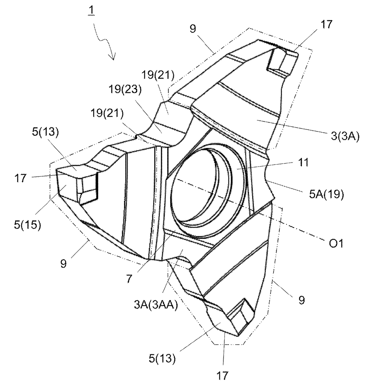
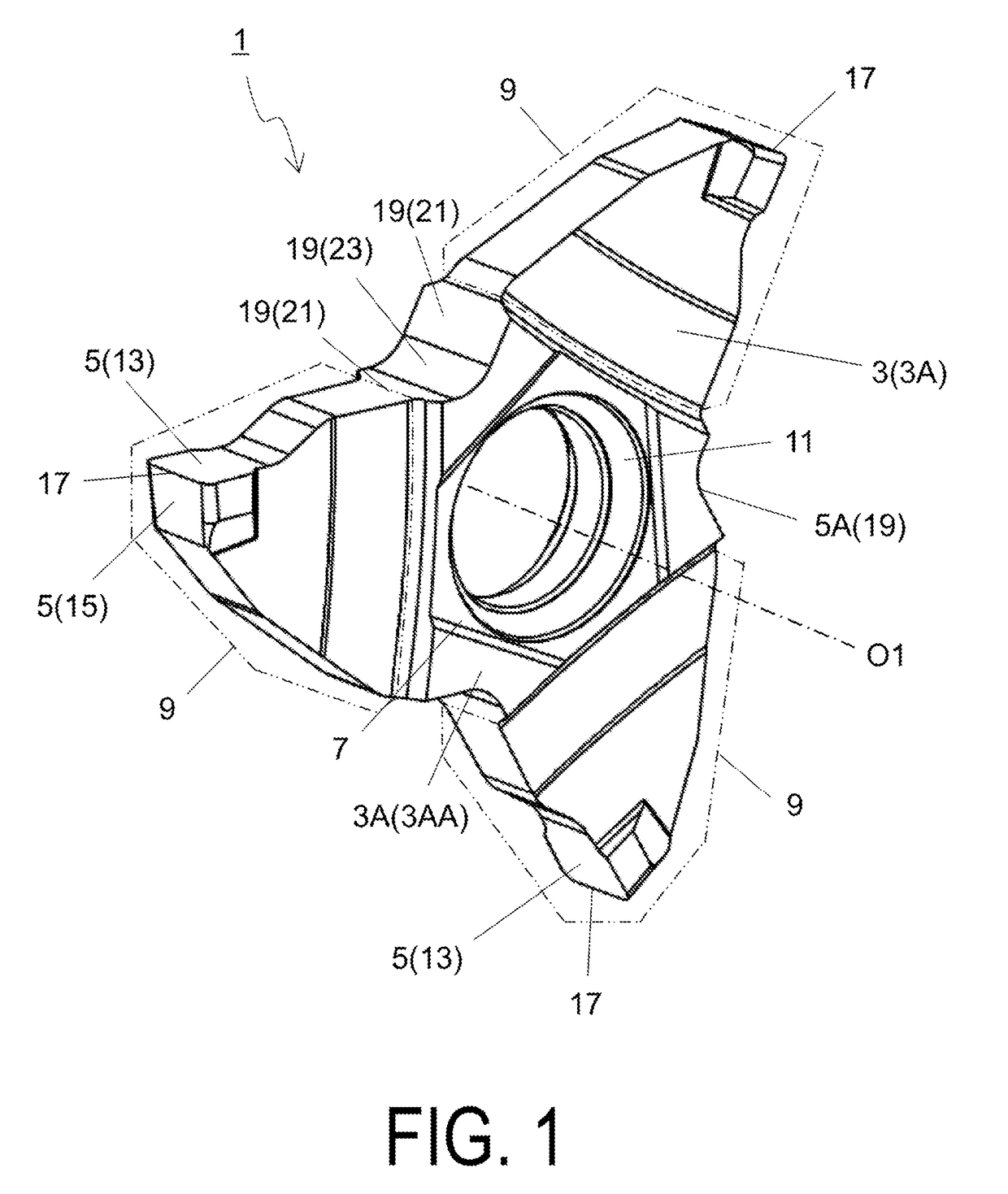
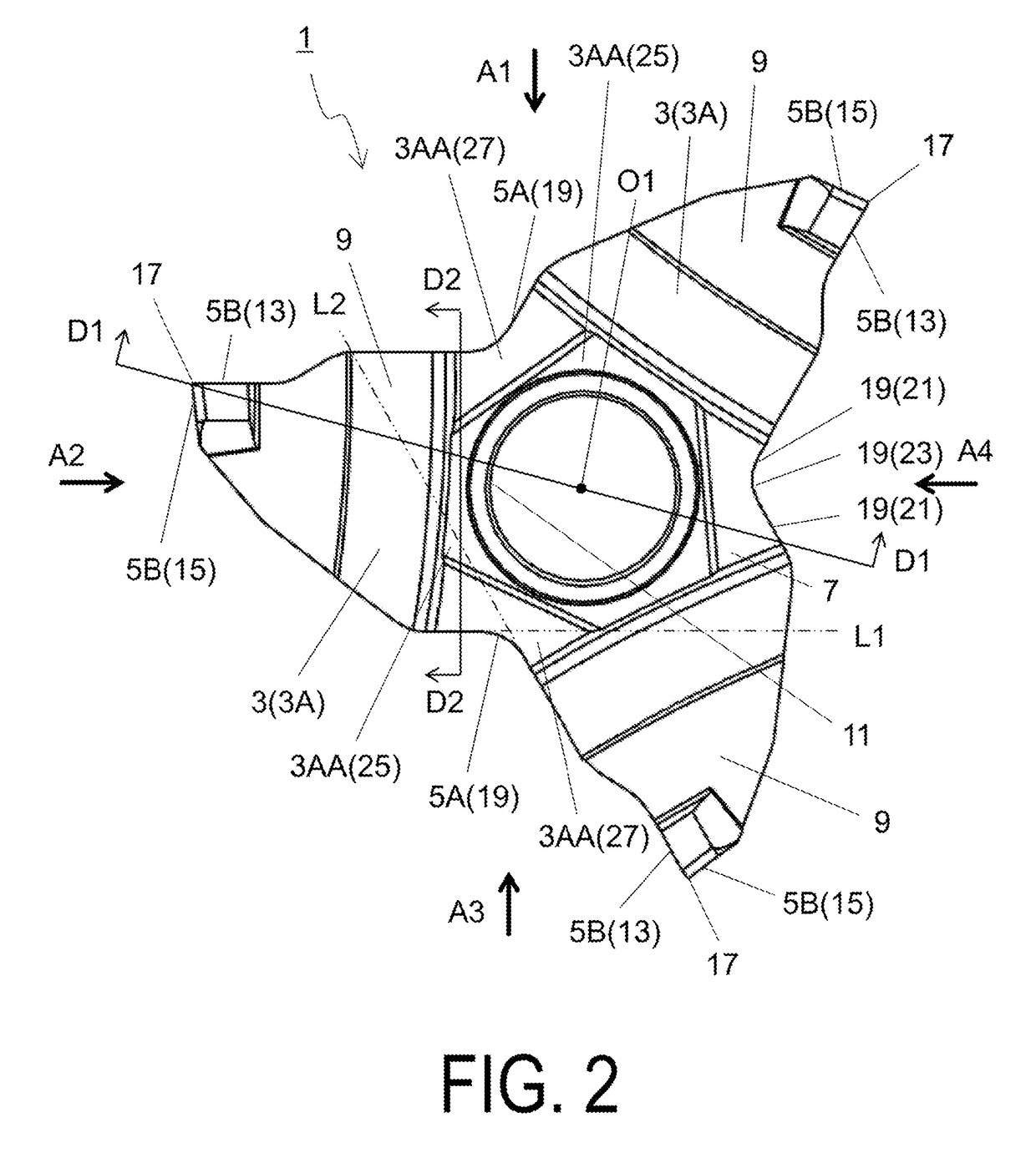
[0025]The following describes in detail a cutting insert 1 of an embodiment while referencing the drawings. However, for ease of explanation, each of the drawings referenced below is simplified and illustrates only the main constituent members needed to describe the present embodiment. Accordingly, the cutting tool of the present invention may be provided with other constituent members which are not illustrated in the referenced drawings. Further, the dimensions of the members in the drawings do not faithfully represent the actual dimensions of the constituent members, the dimension ratios of the members, or the like.

[0026]The cutting insert 1 of the present embodiment (hereinafter also referred to simply as “insert 1”) has a flat plate shape including a pair of polygonal main surfaces 3 and an outer peripheral surface 5 located between the pair of main surfaces 3. In this specification, one of the pair of main surfaces 3 is referred to as a first main surface 3A and the other is re...


PUM


Abstract

A cutting insert according to one aspect has a flat plate shape including a first main surface having a polygonal shape, a second main surface located opposite to the first main surface, and an outer peripheral surface located between the first main surface and the second main surface. The cutting insert includes a cutting portion located in regions including at least a corner portion of the first main surface, and a main body portion located in a region other than the corner portion. A thickness of the main body portion is larger than a thickness of the cutting portions, and the main body portion includes a recessed portion or a protruding portion located in the outer peripheral surface thereof.

Description

TECHNICAL FIELD[0001]An aspect relates to a cutting insert used in machining, a cutting tool, and a method for manufacturing a machined product.BACKGROUND ART[0002]In the related art, throw-away cutting tools such as that described in Japanese Unexamined Patent Application Publication No. 2005-074531 (Patent Document 1) are known as cutting tools used in machining such as grooving and threading. A throw-away tip (cutting insert) of the throw-away cutting tool described in Patent Document 1 has a flat plate shape including two main surfaces with triangular shapes and an outer peripheral surface. Additionally, a recessed portion that engages with a protruding portion of a holder is provided in the outer peripheral surface.[0003]In recent years, a demand has arisen for a cutting insert that can be used for machining where larger loads are applied. With the throw-away tip described in Patent Document 1, the thickness (space between the two main surfaces) of the recessed portion that eng...

Claims


Application Information

Patent Timeline
Patent Type & Authority Applications(United States)
IPC IPC(8): B23B27/04B23B27/06B23B29/04B23B27/14B23B27/16
CPCB23B27/045B23B27/143B23B27/1622B23B27/065B23B29/043B23G2200/10B23B2205/12B23B2200/049B23B2200/369B23C2220/36B23B27/04B23B2200/048B23B2200/121B23B2200/165B23B27/16
Inventor ANDO, YUICHI
Owner KYOCERA CORP
Why Eureka
Try Eureka