Keyswitch with adjustable tactile feedback and switch thereof

a technology of tactile feedback and switches, which is applied in the direction of instruments, sports apparatus, pulse techniques, etc., can solve the problems of high replacement cost, limited flexibility in use and operation convenience of mechanical keyswitch, and high replacement cos

Active Publication Date: 2018-01-04
DARFON ELECTRONICS CORP
View PDF10 Cites 23 Cited by
  • Summary
  • Abstract
  • Description
  • Claims
  • Application Information

AI Technical Summary

Benefits of technology

[0005]The present invention further provides a keyswitch. The keyswitch includes a base, a cap, a sleeve, an elastic member, and a resilient arm. The base has a pillar extending along a Z-axis. The Z-axis, an X-axis and a Y-axis are perpendicular to each other. The cap has a limiting arm. The limiting arm protrudes toward the base along the Z-axis and is movably connected to the base, so as to make the cap movable upward and downward between a high position and a low position along the Z-axis. The resilient arm is adjacent to the pillar. The sleeve abuts against the cap and rotatably sleeves the pillar for rotating on the pillar around the Z-axis. The sleeve has an outer annular surface formed thereon. The outer annular surface has a first convex portion, a first concave portion, a second convex portion, a second concave portion and an arc-shaped bar. The arc-shaped bar extends above the second convex portion but not extends above the first convex portion. The resilient arm selectively abuts against the firs

Problems solved by technology

That is to say, a conventional mechanical keyswitch could only provide one single kind of tactile feedback without a tactile feedback adjusting function.
I

Method used


Image

  • Keyswitch with adjustable tactile feedback and switch thereof
  • Keyswitch with adjustable tactile feedback and switch thereof
  • Keyswitch with adjustable tactile feedback and switch thereof

Examples


Embodiment Construction

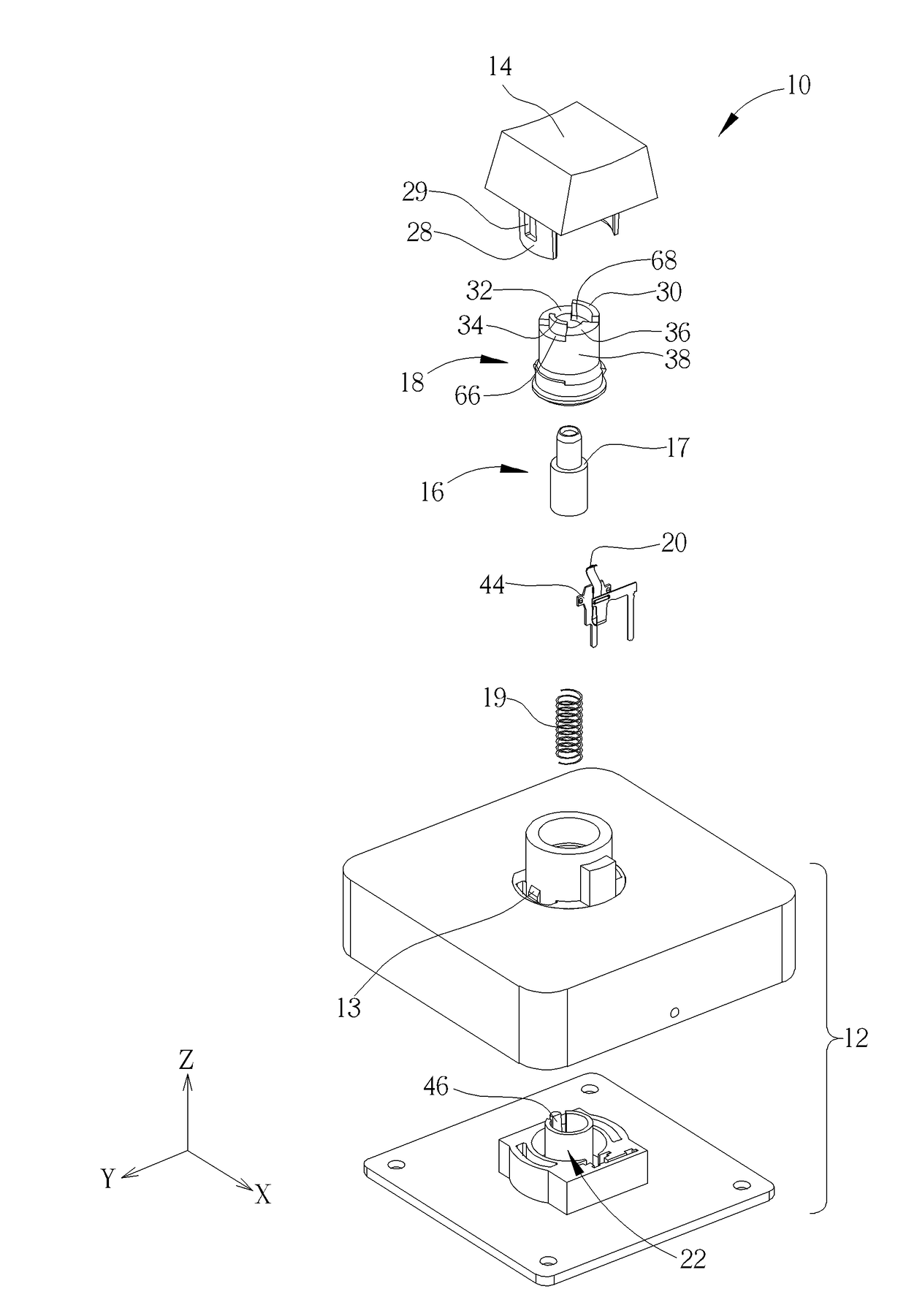
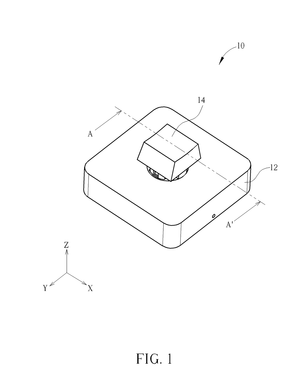
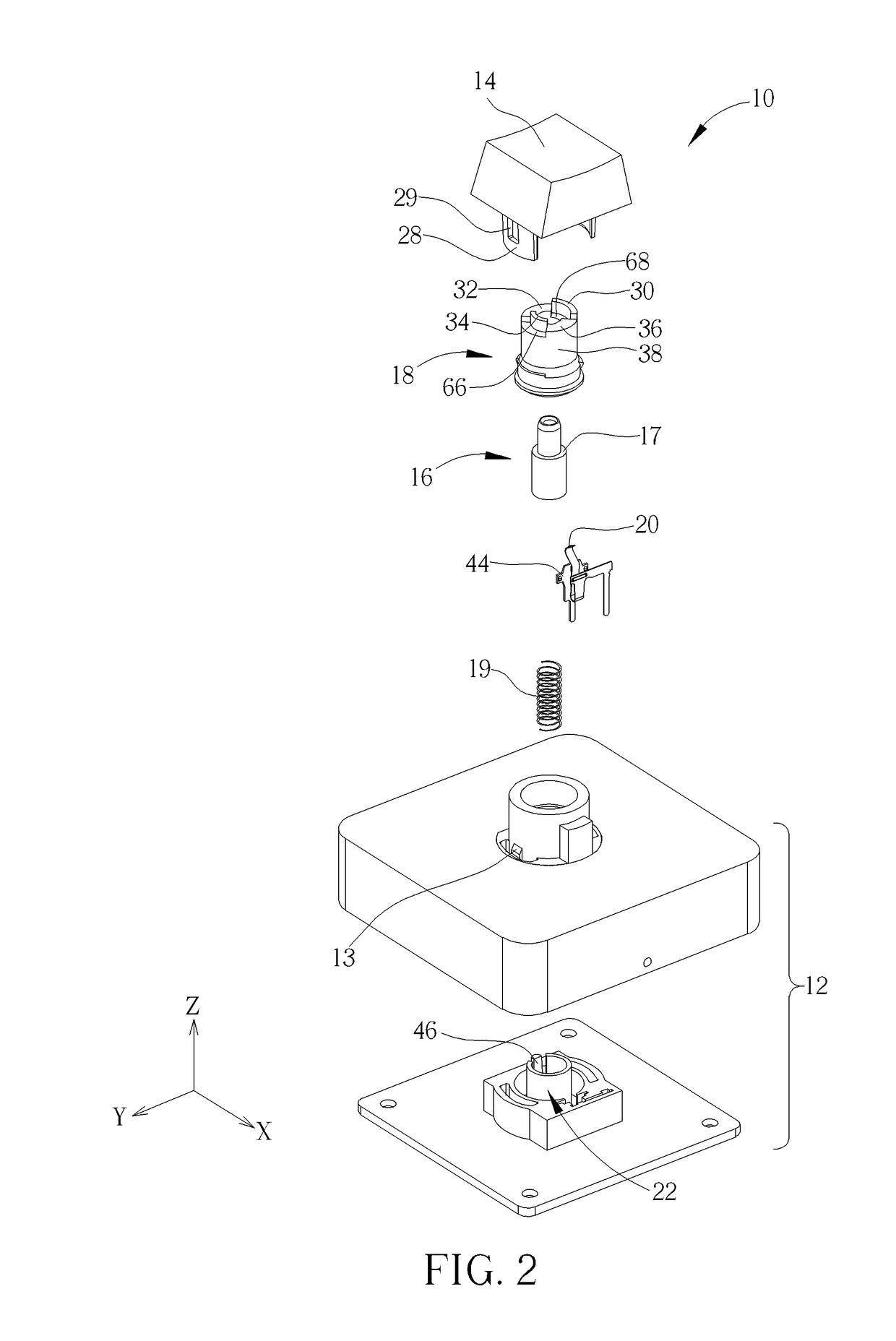
[0051]Please refer to FIG. 1, FIG. 2, FIG. 3, FIG. 4, and FIG. 5. FIG. 1 is a diagram of a keyswitch 10 according to an embodiment of the present invention. FIG. 2 is an exploded diagram of the keyswitch 10 in FIG. 1. FIG. 3 is a cross-sectional diagram of the keyswitch 10 in FIG. 1 along a cross-sectional line A-A′. FIG. 4 is a partial exploded diagram of the keyswitch 10 in FIG. 1. FIG. 5 is a cross-sectional diagram of the cap 14 in FIG. 3 being pressed to a low position. For clearly showing the internal mechanical design of the keyswitch 10, only a bottom half structure is depicted for a base 12 in FIG. 4. As shown in FIG. 1, FIG. 2, FIG. 3, FIG. 4, and FIG. 5, the keyswitch 10 includes the base 12, the cap 14, an internal sleeve 16, an external sleeve 18, an elastic member 19, and a resilient arm 20. The base 12 has a pillar 22. The pillar 22 extends along a Z-axis as shown in FIG. 2. The Z-axis, an X-axis and a Y-axis are perpendicular to each other. The resilient arm 20 is ad...


PUM


Abstract

A keyswitch includes a base having a pillar, a cap having a rib and movable relative to the base, a sleeve rotatably sleeving the pillar and having first and second top surfaces and convex and concave portions, an elastic member abutting against the sleeve and the base, and a resilient arm abutting against a first or second position on the convex portion with rotation of the sleeve. When the resilient arm abuts against the first position, the rib abuts against the first top surface to prepress the elastic member for generating a first preload. When the cap is pressed for moving the sleeve downward, the resilient arm moves from the first or second position to the concave portion. When the resilient arm abuts against the second position, the rib abuts against the second top surface to prepress the elastic member for generating a second preload larger than the first preload.

Description

BACKGROUND OF THE INVENTION1. Field of the Invention[0001]The present invention relates to a keyswitch and a switch thereof, and more specifically, to a keyswitch with an adjustable tactile feedback via rotation of a sleeve relative to a base and a switch thereof.2. Description of the Prior Art[0002]A keyboard, which is the most common input device, could be found in variety of electronic apparatuses for users to input characters, symbols, numerals and so on. Furthermore, from consumer electronic products to industrial machine tools, they are all equipped with a keyboard for performing input operations.[0003]In practical application, there are various kinds of keyswitches for providing different tactile feedbacks. For example, a gaming keyboard would indicates that it has red, brown or black keyswitches installed thereon on its packing box to remind the user of what kind of tactile feedback (e.g. high or low triggering position, long or short travel distance, required actuation forc...

Claims


Application Information

Patent Timeline
IPC IPC(8): H03K17/975H03K17/98H03K17/96H01H13/705H01H13/00
CPCH03K17/975H01H13/705H03K2217/96077H03K17/98H01H13/00H03K17/9622H01H2235/01H01H13/85H01H2231/008H01H2235/016G06F3/0202H01H2215/028G06F3/0216
Inventor LIU, CHIA-HUNG
Owner DARFON ELECTRONICS CORP
Why Eureka
Try Eureka