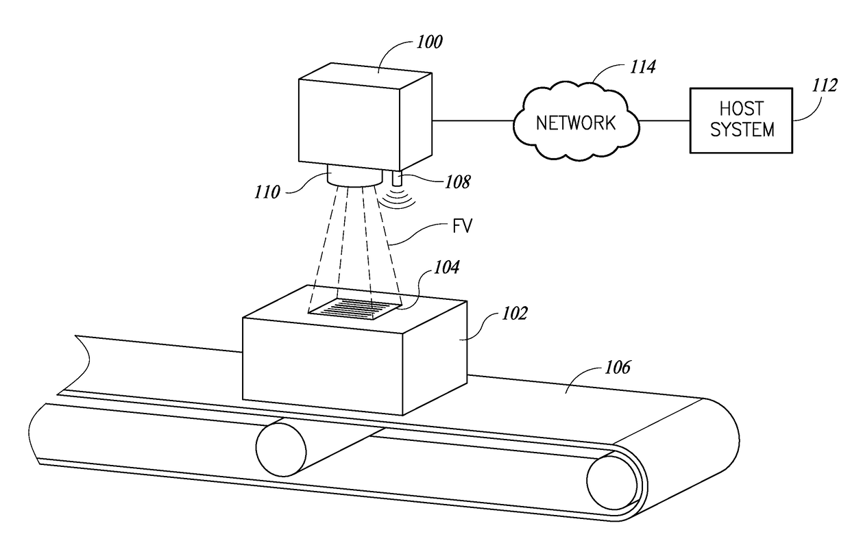
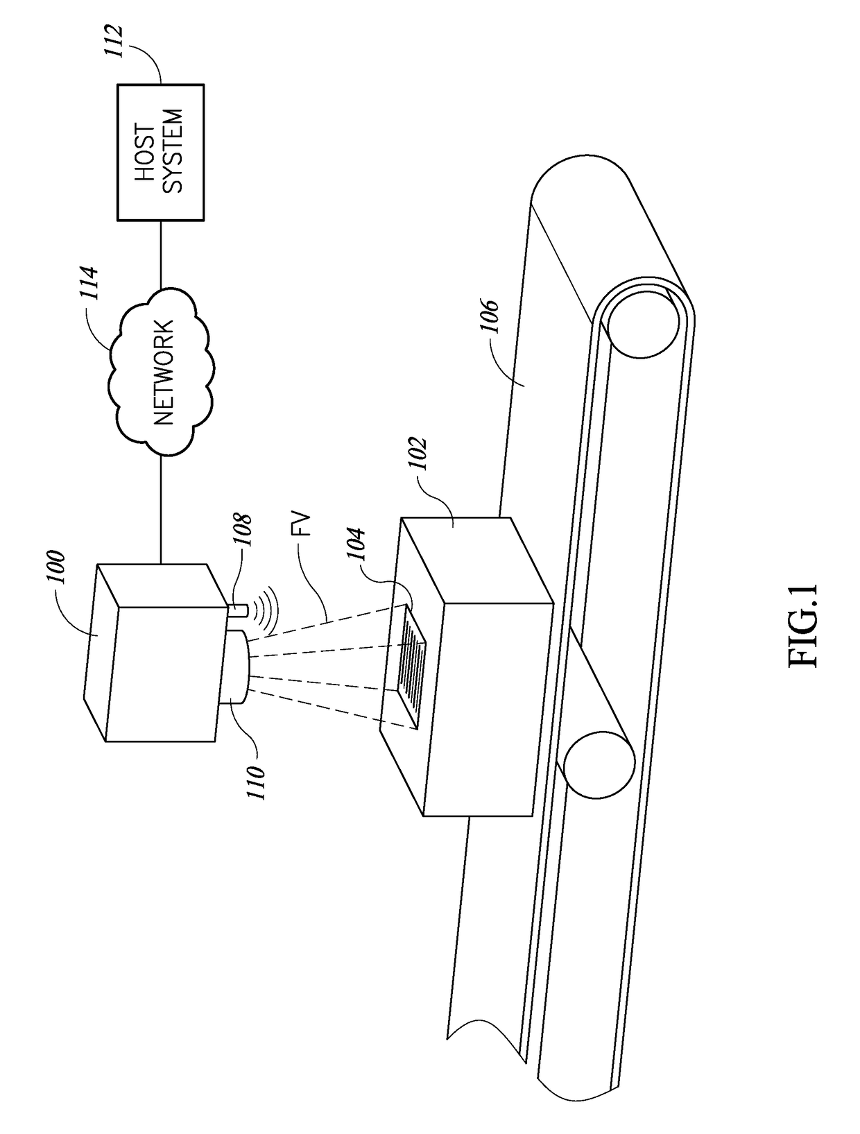
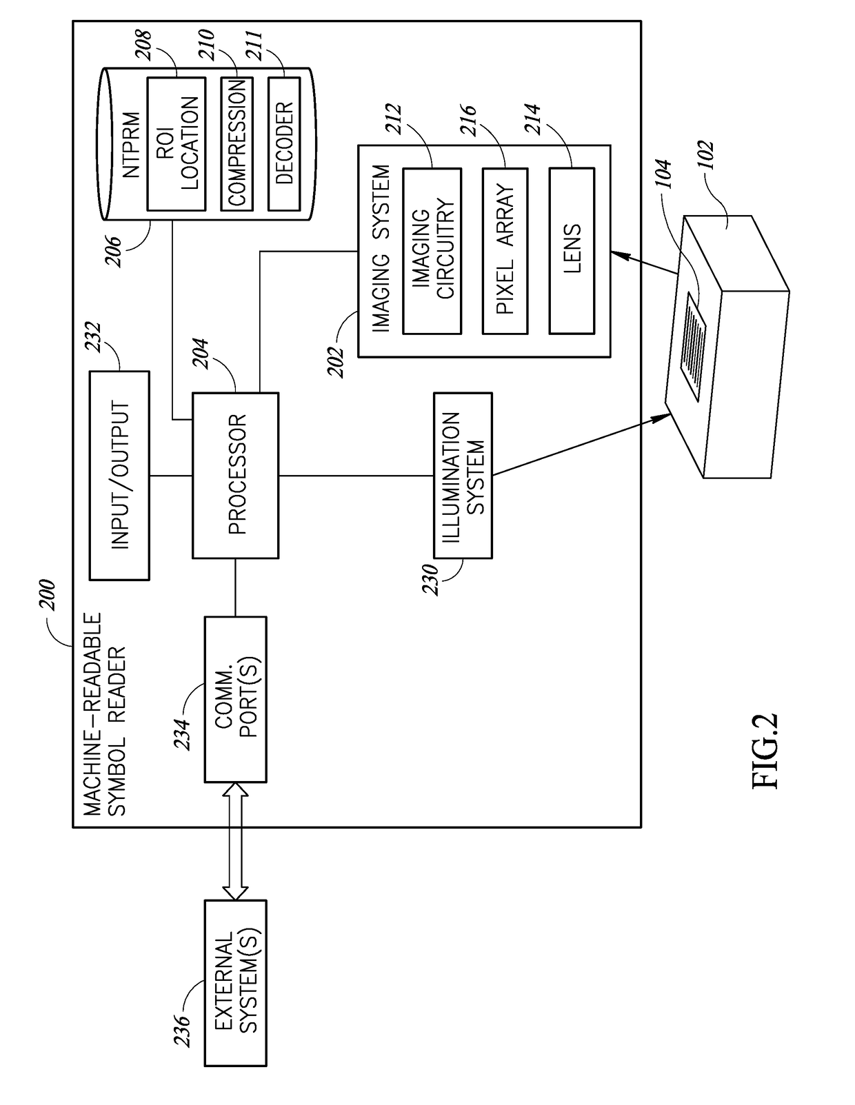
Region of interest location and selective image compression

a region of interest and selective image technology, applied in the field of image processing and compression, can solve the problems of destroying potentially important information in the image, using these techniques, and unable to send substantially real-time images to other processor-based devices over a data communication channel (e.g., lan, wan)

Active Publication Date: 2018-01-18
DATALOGIC USA INC
View PDF3 Cites 0 Cited by
  • Summary
  • Abstract
  • Description
  • Claims
  • Application Information

AI Technical Summary

Benefits of technology

The patent describes a method for processing an image file using an image processor system. The method involves partitioning the image file into regions, binarizing the image file to create a binary image file, and correlating each pixel in the binary image file with its neighbors to identify regions of interest. The method also includes blurring the image file to create a blurred region correlation array, comparing the region correlation value with a region of interest threshold, and identifying the region as a region of interest if the region correlation value is above the threshold. The method can be used to identify specific regions of interest in an image file and improve image processing efficiency.

Problems solved by technology

Thus, sending images from the camera to other processor-based devices in substantially real-time over a data communications channel (e.g., LAN, WAN) can be difficult or impossible.
However, using these techniques has disadvantages due to the loss of information in the images.
For instance, JPEG conversion, while providing a reasonable representation of the original image, still destroys potentially important information in the image, such as binarized data encoded in the pixel least significant bit (LSB), which may be used for optical character recognition (OCR), or embedded data typically placed in the scan line which provides information regarding camera operation relating to the image being acquired.
Further, image cropping is not always reliable as part of the object or data of interest may be cropped.
Such functions are computationally intensive, and such functions do not assist in compression of the images.

Method used


Image

  • Region of interest location and selective image compression
  • Region of interest location and selective image compression
  • Region of interest location and selective image compression

Examples


Embodiment Construction

[0046]In the following description, certain specific details are set forth in order to provide a thorough understanding of various disclosed implementations. However, one skilled in the relevant art will recognize that implementations may be practiced without one or more of these specific details, or with other methods, components, materials, etc. In other instances, well-known structures associated with computer systems, server computers, and / or communications networks have not been shown or described in detail to avoid unnecessarily obscuring descriptions of the implementations.

[0047]Unless the context requires otherwise, throughout the specification and claims that follow, the word “comprising” is synonymous with “including,” and is inclusive or open-ended (i.e., does not exclude additional, unrecited elements or method acts).

[0048]Reference throughout this specification to “one implementation” or “an implementation” means that a particular feature, structure or characteristic de...


PUM


Abstract

Systems and methods of operation for an image processor system to process images to locate two-dimensional regions which are likely to contain machine-readable symbol data or text. Such regions of interest (ROIs) may be preserved at full resolution, whilst the contents of non-ROIs are averaged into a single pixel value. Transition densities in an image may be converted into a numeric value. Such transition densities may be indicative of the presence of data of interest, such as textual data and / or machine-readable symbol data. The pixels values for the pixels in the ROIs may be sent to a decoder unchanged (i.e., full resolution), which absolves the decoder from having to perform any ROI location computations. Modified or altered images may be compressed to much smaller size files while maintaining lossless ROIs, which allows for transmission of such images to processor-based devices over a data communications channel in real time.

Description

BACKGROUNDTechnical Field[0001]The present disclosure generally relates to image processing and compression.Description of the Related Art[0002]Machine-readable symbols encode information in a form that can be optically read via a machine-readable symbol reader or scanner. Machine-readable symbols take a variety of forms, the most commonly recognized form being the linear or one-dimensional machine-readable symbol. Other forms include two-dimensional machine-readable symbols such as stacked code symbols, area or matrix code symbols, or machine-readable symbols. These machine-readable symbols may be made of patterns of high and low reflectance areas. For instance, a one-dimensional barcode symbol may comprise a pattern of black bars on a white background. Also for instance, a two-dimensional symbol may comprise a pattern of black marks (e.g., bars, squares or hexagons) on a white background. Machine-readable symbols are not limited to being black and white, but may comprise two other...

Claims


Application Information

Patent Timeline
Patent Type & Authority Applications(United States)
IPC IPC(8): G06K7/14G06K9/32G06K7/10H04N1/00G06V10/25
CPCH04N1/00G06K9/3233G06K7/1495G06K7/1417G06K7/1413G06K7/10821G06K7/10732G06V10/25
Inventor GAGLIANO, JEFFREY A.
Owner DATALOGIC USA INC
Why Eureka
Try Eureka