Clock and data recovery circuit and frequency detection method thereof

a clock and data recovery circuit technology, applied in the field of detection methods, can solve problems such as cdr circuits, and achieve the effect of increasing or decreasing the frequency of clock signals

Active Publication Date: 2017-06-20
REALTEK SEMICON CORP
View PDF8 Cites 0 Cited by
  • Summary
  • Abstract
  • Description
  • Claims
  • Application Information

AI Technical Summary

Benefits of technology

[0007]An exemplary embodiment of the present disclosure provides a crystal-less clock and data recovery (CDR) circuit including a clock generator and a frequency detection module. The clock generator operatively generates a clock signal. The frequency detection module is coupled to the clock generator. The frequency detection module operatively generates and outputs a control signal to the clock generator according to a data signal received and a transition density, so as to increase or decrease the frequency of the clock signal generated by the clock generator.
[0009]An exemplary embodiment of the present disclosure provides a frequency detection method for a crystal-less CDR circuit, wherein the crystal-less CDR circuit includes a clock generator and a frequency detection module. The frequency detection method includes the following steps. The clock generator is first driven to generate a clock signal. The frequency detection module is driven to output a control signal thereafter to the clock generator according to a data signal received and a transition density, so as to increase or decrease the frequency of the clock signal generated by the clock generator.
[0011]To sum up, the crystal-less CDR circuit and the frequency detection method provided by the present disclosure is capable of accurately detecting the clock frequency of the data signal received and directly calibrating the clock signal generated by the built-in clock generator, accordingly, without referencing an external-supplied reference clock signal to adjust the clock signal generated by the built-in clock generator. Accordingly, the cost for design the overall system architecture can be lowered.

Problems solved by technology

For example, when the frequency of an initial clock signal is too low, causing distortion in the sampling result, the CDR circuit generates a control signal to drive the clock generator to increase the frequency of the clock signal.
However, the clock generator, being built-in the CDR circuit, is known to be vulnerable to variations in semiconductor processing, temperature, and voltage generating the problem of frequency drifting.

Method used


Image

  • Clock and data recovery circuit and frequency detection method thereof
  • Clock and data recovery circuit and frequency detection method thereof
  • Clock and data recovery circuit and frequency detection method thereof

Examples


Embodiment Construction

[0026]Reference will now be made in detail to the exemplary embodiments of the present disclosure, examples of which are illustrated in the accompanying drawings. Wherever possible, the same reference numbers are used in the drawings and the description to refer to the same or like parts.

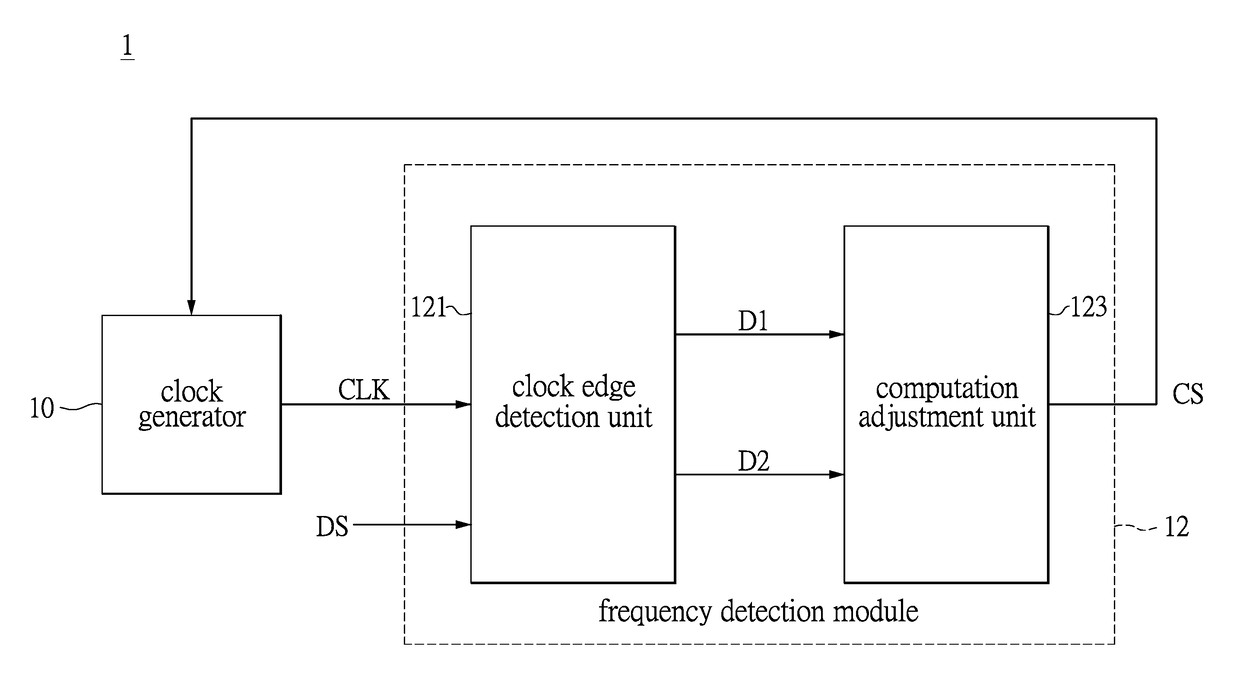
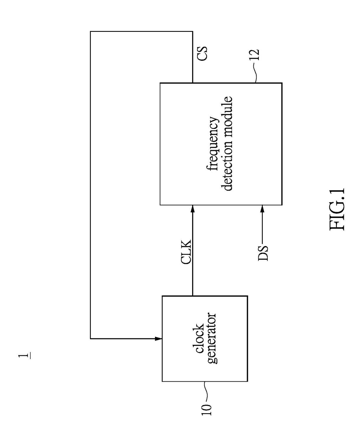
[0027]Please refer to FIG. 1, which shows a block diagram illustrating a clock and data recovery circuit provided in accordance with an exemplary embodiment of the present disclosure. The clock and data recovery (CDR) circuit 1 includes a clock generator 10 and a frequency detection module 12. The frequency detection module 12 is coupled to the clock generator 10. The above described components can be integrated or separately disposed and the instant disclosure is not limited thereto.

[0028]The clock generator 10 is configured to operatively generate a clock signal CLK. The frequency detection module 12 is configured to generate a control signal CS according to a transition density TD and a data sign...


PUM


Abstract

The present disclosure provides a crystal-less clock and data recovery (CDR) circuit and a frequency detection method thereof. The CDR circuit includes a clock generator and a frequency detection module. The clock generator is operable to generate a clock signal. The frequency detection module coupled to the clock generator is configured for outputting a control signal to the clock generator to increase or decrease the frequency of the clock signal according to a data signal received and a transition density.

Description

BACKGROUND[0001]1. Technical Field[0002]The present disclosure relates to a detection method in particular, to a frequency detection method used for a clock and data recovery (CDR) circuit operating without referencing an external reference clock signal.[0003]2. Description of Related Art[0004]In a general communication system, a transmitter operatively generates a data signal according to the clock signal at the transmitter and transmits the data signal to a receiver through a wireless or wired transmission medium. In order for the receiver to correctly identify the logic level (e.g., 0 or 1) of the data signal, the receiver has to read the data signal received after the clock signal at the receiver had synchronized with the clock signal at the transmitter. Conventionally, the receiver includes a clock and data recovery (CDR) circuit for recovering the clock signal at the receiver to be identical to the clock signal at the transmitter.[0005]Generally, at least one clock generator i...

Claims


Application Information

Patent Timeline
Patent Type & Authority Patents(United States)
IPC IPC(8): H03D3/24H04L7/033H04L25/49
CPCH04L25/49H04L7/0331
Inventor CHANG, FENG-CHENGZHENG, XIAO-GUO
Owner REALTEK SEMICON CORP
Why Eureka
Try Eureka