Biomolecule analyzing system

a biomolecule and analysis system technology, applied in the field of biomolecule analysis systems, can solve the problems of insufficient sequencing of long dna strands, difficult and error-prone task of overlapping fragments into a complete genome, and the length of linear track is the limit of the dna fragment that can be moved, so as to increase or decrease the frequency of observations

Inactive Publication Date: 2009-04-30
PARKER JOHN A +1
View PDF17 Cites 0 Cited by
  • Summary
  • Abstract
  • Description
  • Claims
  • Application Information

AI Technical Summary

Benefits of technology

[0038]The piezoelectric effect inherent in the crystal substrate itself, or a second crystal, can be stimulated by a charge to generate an oscillation in each of the anti-parallel sensors. By modifying the amplitude of the charge applied to the crystal, a minimum and maximum oscillation will control the size of the sensor space and frequency at which the cilia contact the biomolecules in the sensor space. This can be used to increase or decrease the frequency of observations recorded.

Problems solved by technology

Unfortunately, the above-described process is inadequate for the sequencing of long DNA strands.
Even if the entire sequence of each fragment were known, the task of overlapping the fragments into a complete genome would be a difficult and error prone.
The only limitation to the length of a DNA fragment that can be moved is the length of the linear track.

Method used


Image

  • Biomolecule analyzing system
  • Biomolecule analyzing system
  • Biomolecule analyzing system

Examples


Embodiment Construction

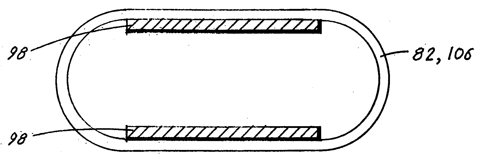
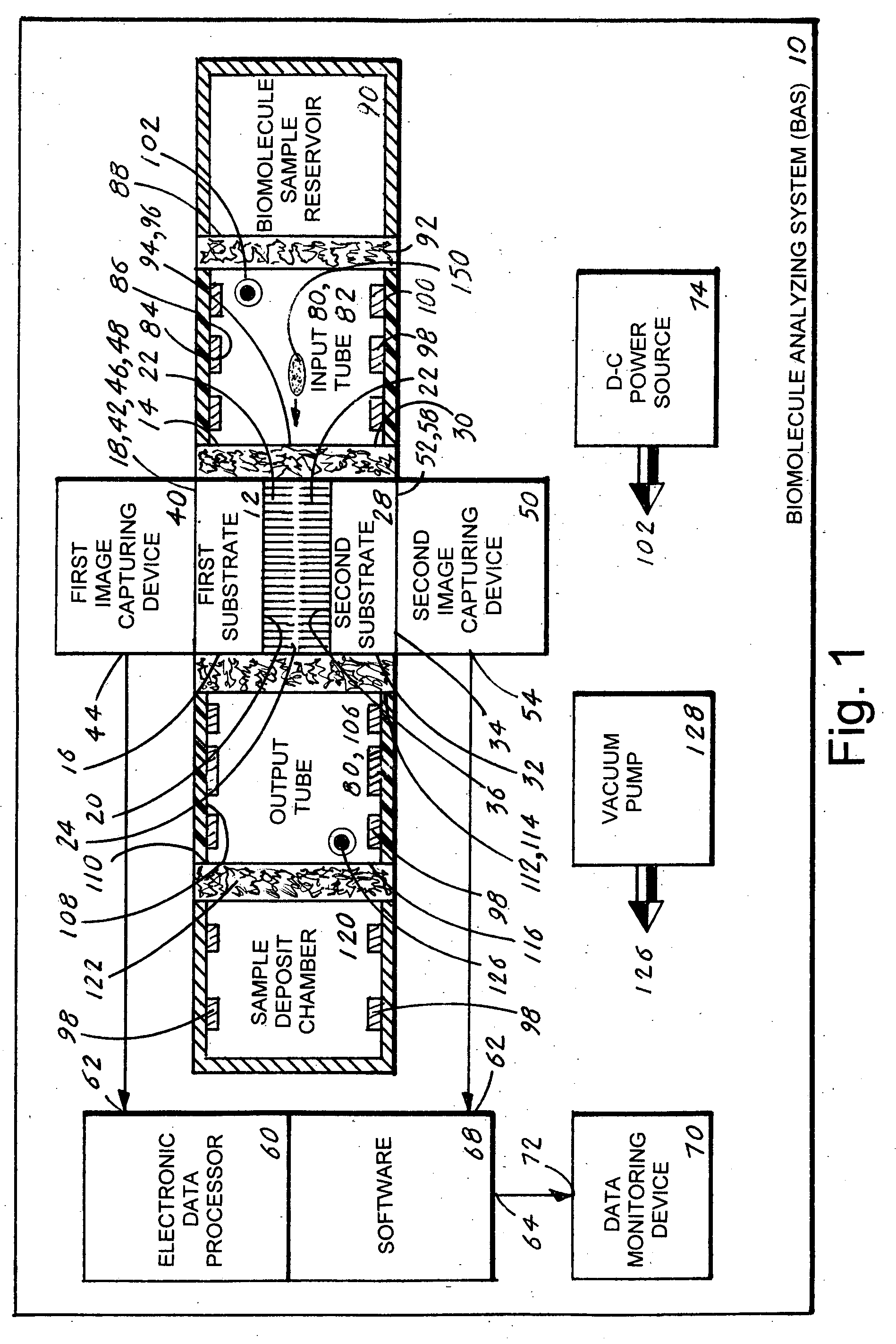
[0047]The best mode for carrying out the invention is presented in terms of a preferred embodiment for a biomolecule analyzing system 10 (hereinafter “BAS 10”). The BAS 10, as shown in FIGS. 1-4, is comprised of the following major elements: a first substrate 12, a second substrate 28, a first image capturing device 40, a second image capturing device 50, an electronic data processor 60, software 68, a data monitoring device 70, a d-c power source 74 and a biomolecule traversing track 80.

[0048]The first substrate, as shown in FIG. 1, includes an inner edge 14, an outer edge 16, an outer surface 18, and an inner surface 20. From the inner surface 20 extends downward a multiplicity of cilia 22, with each cilium 22 having a uniform length and terminus 24.

[0049]The second substrate 28, as shown in FIG. 1, includes an inner edge 30, an outer edge 32, an outer surface 34 and an inner surface 36. From the inner surface 36 extends upward a multiplicity of cilia 22, with each cilium 22 also ...


PUM

PropertyMeasurementUnit
lengthaaaaaaaaaa
diameteraaaaaaaaaa
heightaaaaaaaaaa

Abstract

A biomolecule analyzing system (10) that provides an expeditious, accurate and reliable method for analyzing a biomolecule (150). The system (10) includes two substrates (12,28) each having an inner edge (14,30), an outer edge (16,32) and an inner surfaces (20,36) from where extends a multiplicity of cilia (22). To the inner edges (14,30) is attached an input tube (82) that is also attached to a biomolecule sample reservoir (90). To the outer edges (16,32) is attached an output tube (106) that is also attached to a sample deposit chamber (120). The tubes (82,106) include a plurality of conductive plates (98) that are applied an electrical charge that causes the biomolecule (150) to traverse through the tubes (82,106). When the biomolecule (150) passes through the cilia (22) signals are produced that are applied to a pair of image capturing devices (40,50). Each device (40,50) produces a signal that is applied to an electronic data processor from where a three-dimensional image of the biomolecule (150) is produced and viewed on a data monitoring device (70).

Description

TECHNICAL FIELD[0001]The invention generally pertains to the field of biomolecule analyzing systems, and more particularly to a biomolecule analyzing system that utilizes a pair of ciliated sensors to produce a three-dimensional image of a biomolecule under study.BACKGROUND ART[0002]In the fields of molecular biology, biochemistry and pharmacology an accurate and expeditious analysis of biomolecules such as recombinant deoxyribonucleic acid (DNA) is of the utmost importance: Typically, a DNA specimen is analyzed by placing the specimen into a porous gel matrix, which allows the movement of particles but impedes the rate of travel. A current is then applied to the gel matrix to produce positively and negatively charged ends of the gel matrix. Under these conditions the DNA migrates toward the positively charged end of the gel matrix. This process is used to separate DNA of different sizes and to separate newly synthesized DNA strands with labels in order to elucidate sequences of sma...

Claims


Application Information

Patent Timeline
Patent Type & Authority Applications(United States)
IPC IPC(8): C12M1/34
CPCB01L3/50273B01L2400/0484B01L2200/0663B01L3/502761Y10S977/902Y10S977/92Y10S977/924Y10S977/953Y10S977/957Y10S977/958
Inventor PARKER, JOHN A.VANDEMORTEL, MIKE
Owner PARKER JOHN A
Why Eureka
Try Eureka