Clock and data recovery circuit

a clock signal and data recovery technology, applied in exclusive-or circuits, digital transmission, generating/distributing signals, etc., can solve the problems of adding complexity and cost to the fll circuit, and the approach cannot be applied to recover the clock signal associated with the input nrz data signal, not other input data signals

Active Publication Date: 2019-08-08
PHOTONIC TECH SHANGHAI CO LTD
View PDF2 Cites 1 Cited by
  • Summary
  • Abstract
  • Description
  • Claims
  • Application Information

AI Technical Summary

Benefits of technology

[0015]In one exemplary embodiment, there is provided a machine-readable tangible and non-transitory medium having information, wherein the information, when read by a hardware processor system, causes the hardware processor system to perform following: generating a plurality of sampled signals by sampling a data signal according to different clock signals; and providing one or more control signals indicating whether to decrease or increase a frequency of one of the different clock signals based on the plurality of sampled signals.

Problems solved by technology

The requirement for the reference clock signal may, however, add complexity and cost to the FLL circuit.
In other words, this approach can only be applied to recover the clock signal associated with the input NRZ data signal, not other input data signals.

Method used


Image

  • Clock and data recovery circuit
  • Clock and data recovery circuit
  • Clock and data recovery circuit

Examples


Embodiment Construction

[0046]Reference will now be made in detail to the embodiments of the present disclosure, examples of which are illustrated in the accompanying drawings. While the present disclosure will be described in conjunction with the embodiments, it will be understood that they are not intended to limit the present disclosure to these embodiments. On the contrary, the present disclosure is intended to cover alternatives, modifications, and equivalents, which may be included within the spirit and scope of the present disclosure as defined by the appended claims.

[0047]In addition, in the following detailed description of embodiments of the present disclosure, numerous specific details are set forth in order to provide a thorough understanding of the present disclosure. However, it will be recognized by one of ordinary skill in the art that the present disclosure may be practiced without these specific details. In other instances, well-known methods, procedures, components, and circuits have not...


PUM


Abstract

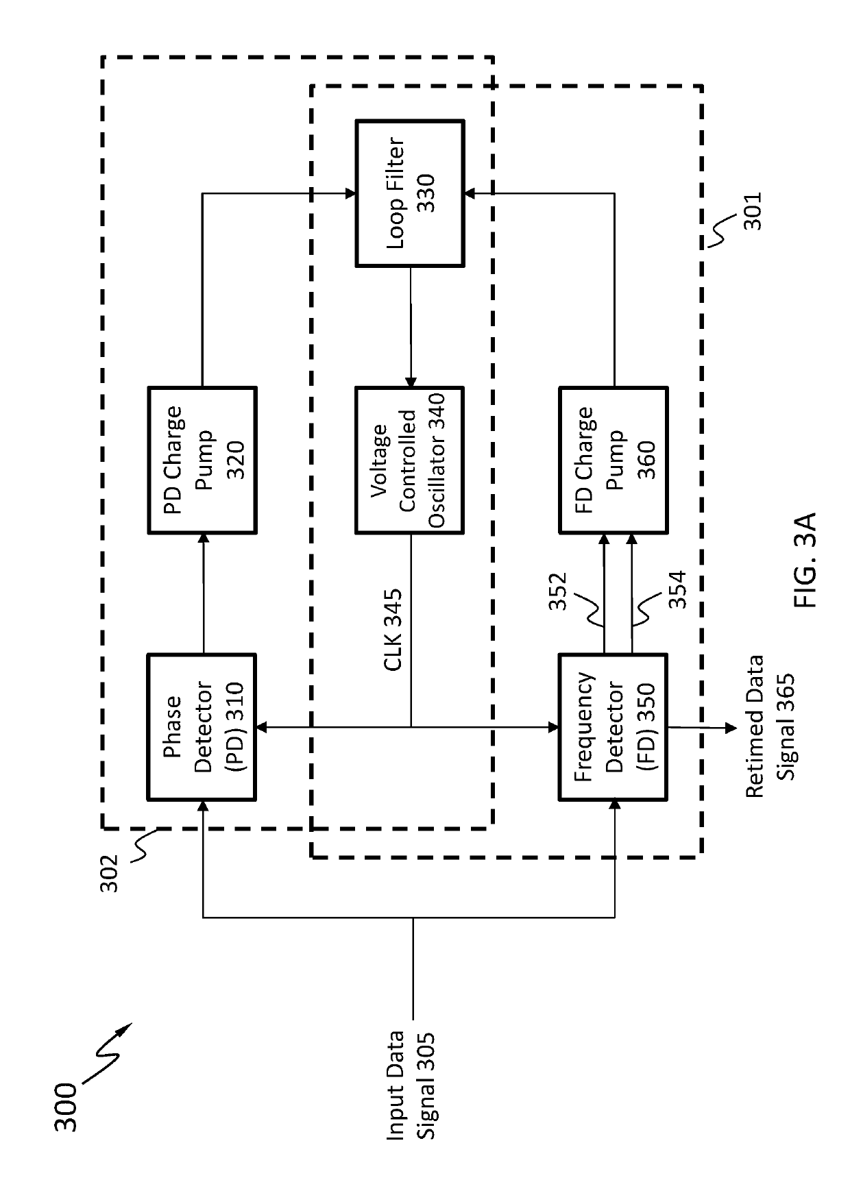
An apparatus comprises a plurality of sampling circuits configured to receive a non-Non Return to Zero (non-NRZ) data signal; and a control circuit coupled to the plurality of sampling circuits, wherein the control circuit is configured to provide one or more control signals indicating whether to decrease or increase a frequency of a clock signal associated with the non-NRZ data signal based on the non-NRZ data signal.

Description

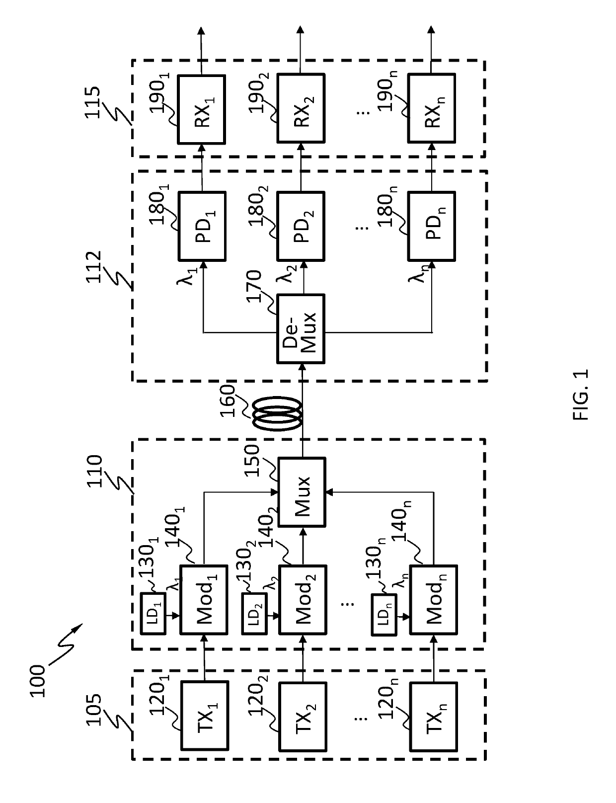
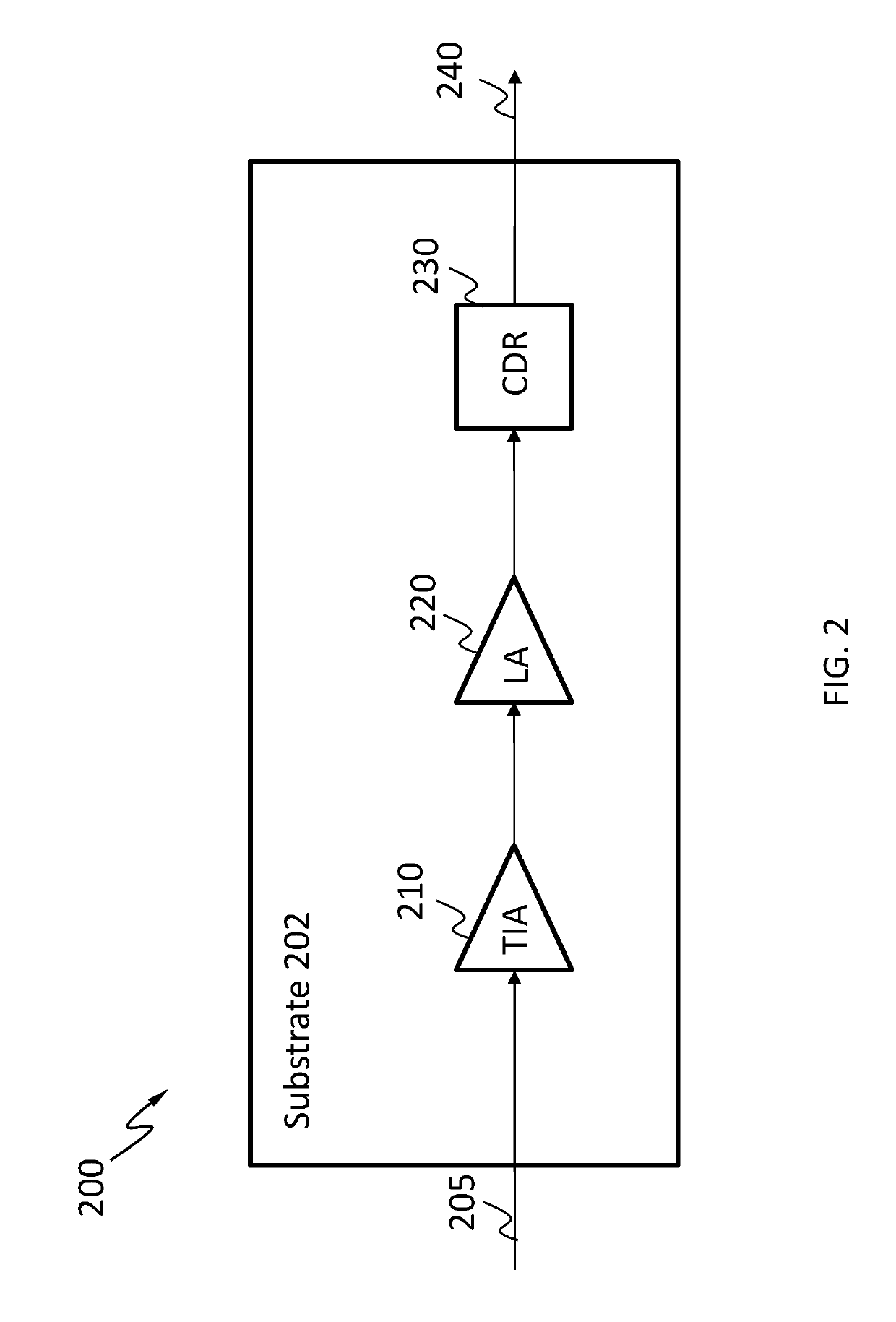
CROSS REFERENCE TO RELATED APPLICATION[0001]This application is a continuation of PCT patent application No. PCT / CN2017 / 096827, filed Aug. 10, 2017, entitled “A Clock and Data Recovery Circuit,” which is hereby incorporated by reference in its entirety.BACKGROUND1. Technical Field[0002]The present disclosure relates generally to methods and apparatuses for clock and data recovery (CDR). In particular, the present disclosure relates to methods and apparatuses suitable for recovering a clock signal upon receipt of an input data signal, and further providing a retimed data signal based on the clock signal and the input data signal.2. Discussion of Technical Background[0003]A CDR circuit has been widely used in a telecommunication system. Upon receipt of a Non Return to Zero (NRZ) data signal, the CDR circuit may be used to recover a clock signal associated with the NRZ data signal, and further retime the received NRZ data signal based on the recovered clock signal. Alternatively or in ...

Claims


Application Information

Patent Timeline
Patent Type & Authority Applications(United States)
IPC IPC(8): H04L7/033H03L7/08H03L7/091H03L7/093H04B14/02H04L25/49
CPCH04L7/033H03L7/0807H03L7/091H03L7/093H04B14/026H04L25/4902H03K19/21H03K19/20H03L7/087H03L7/0891H04L7/02H03L7/099G06F1/06G06F1/12H04L7/0037H04L7/0087H04L7/0331H04B10/25H04B10/548
Inventor BAI, RUICHEN, XUEFENGPAN, WENZONGWANG, XINXIA, TAOHU, SHANGWANG, ZHICHUNZHANG, YUANXIHE, WENJUNWANG, JUNCHENGCHIANG, PATRICK YIN
Owner PHOTONIC TECH SHANGHAI CO LTD
Why Eureka
Try Eureka