
Transition-density based time measurement method

a time measurement and density technology, applied in the direction of pulse characteristics measurement, amplitude demodulation, line-faulst/interference reduction, etc., can solve the problem of large inter-symbol interference in data signals, difficult to make a correct pattern match, and difficult to accurately measure tim

Active Publication Date: 2005-10-20
TEKTRONIX INC
View PDF9 Cites 0 Cited by
  • Summary
  • Abstract
  • Description
  • Claims
  • Application Information

AI Technical Summary

Benefits of technology

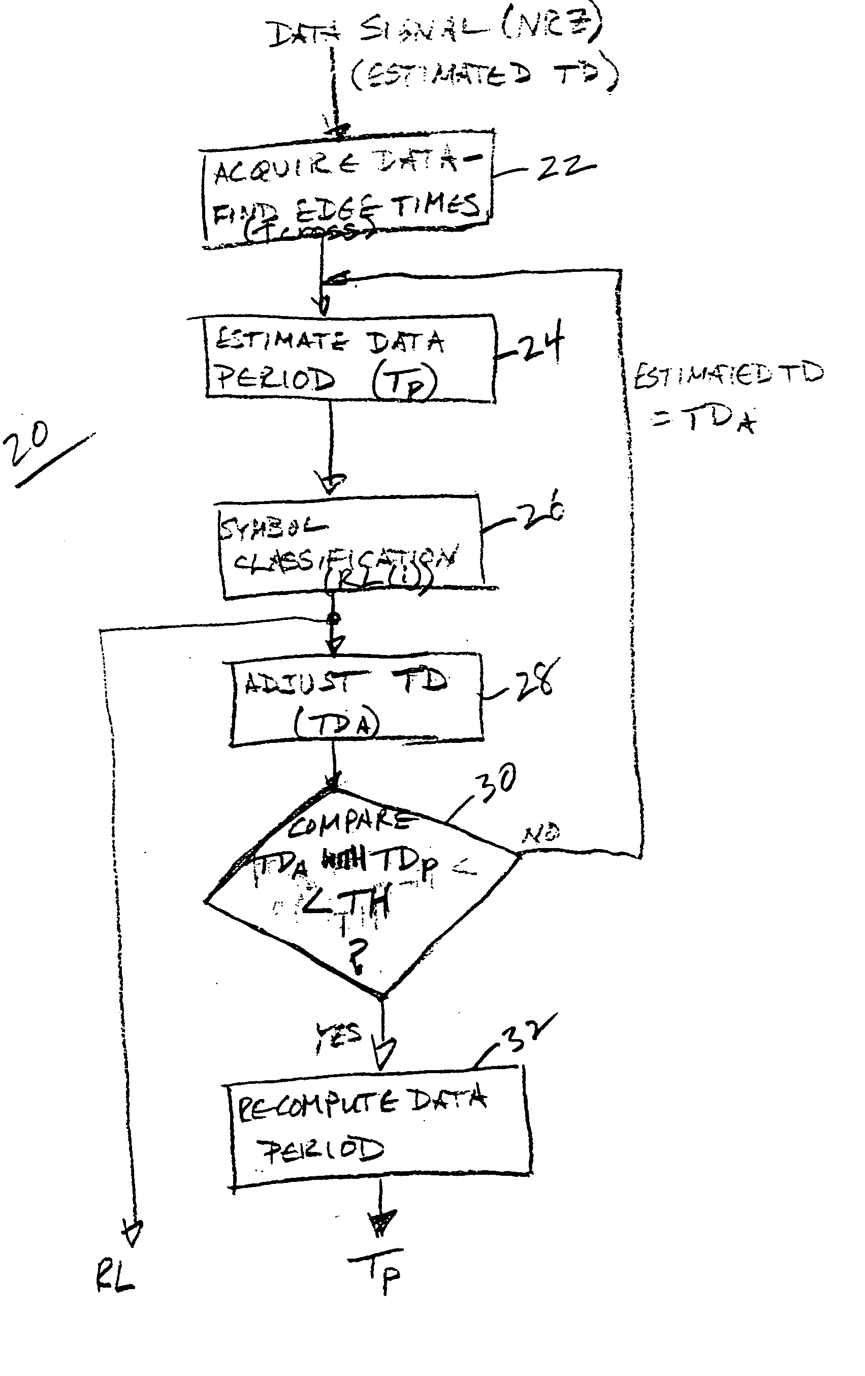
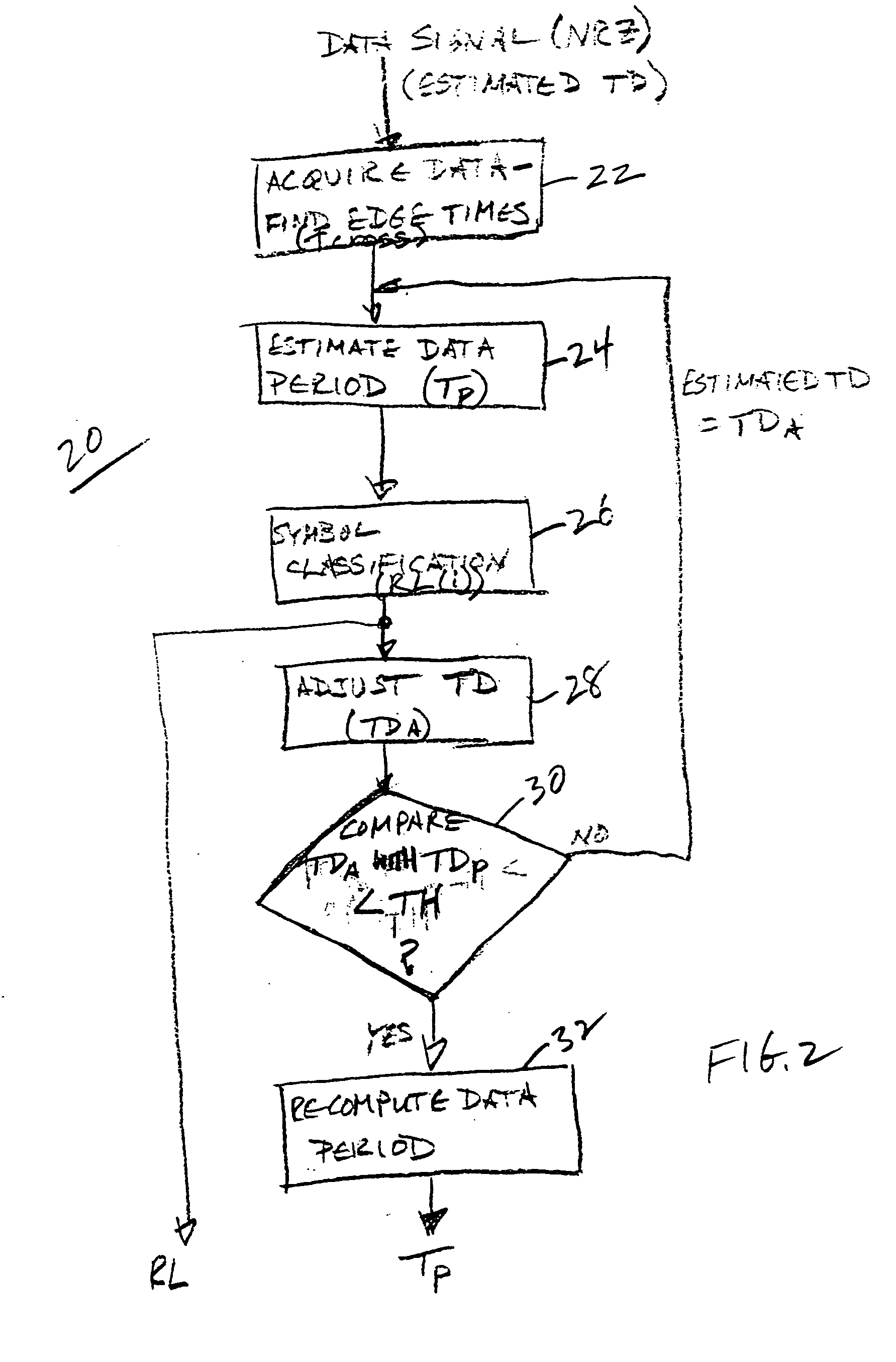
[0007] Accordingly the present invention provides a transition-density (TD) based time measurement method based on the observation that the TD value of a signal is not affected by jitter. Edge crossing times for an acquired data signal are found, and an estimated data period is determined based on such edge crossing times and an initial estimate of the TD value for the data signal. Symbol classification is performed using the estimated data period and edge crossing times to provide a run length array representing

Problems solved by technology

In a high-speed data transfer system it is not uncommon for a data signal to have a large amount of inter-symbol interference (ISI) and other forms of jitter at a receiver.
When the jitter on the data signal occupies a significant percentage of the data period, accurate time measurements are a challenging task.
When the data signal has a large amount of jitter, which could be ISI, periodic jitter (PJ), duty-cycle-distortion (DCD), random jitter (RJ) or a combination of these jitter components, the data time measurement method based on pattern match, as described in U.S. Pat. No. 6,356,850 entitled “Method and Apparatus for Jitter Analysis” by WaveCrest Corporation, has difficulty making a correct pattern match because of the high noise level.
Getting a good estimation of the data period for the pattern match algorithm to start with is also difficult in this case.
The histogram-based method has difficulty avoiding bias when the data signal has large jitter, particularly large ISI.
For a 23-bit pseudo-random binary sequence (PRBS) with a pattern length of roughly eight million, pattern match is quite expensive computationally.

Method used


Image

  • Transition-density based time measurement method
  • Transition-density based time measurement method
  • Transition-density based time measurement method

Examples


Embodiment Construction

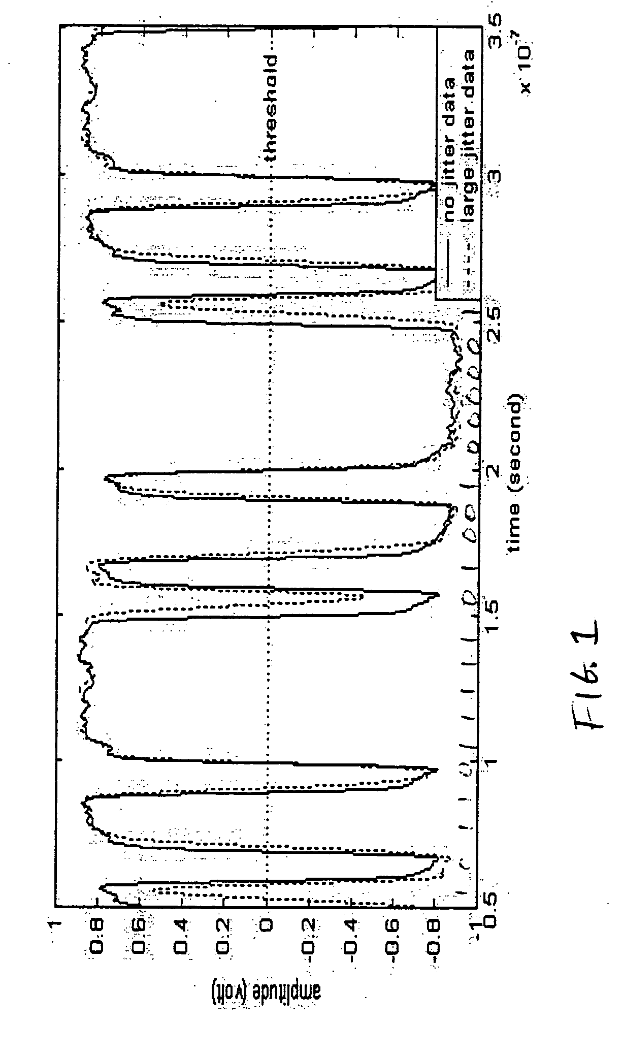
[0011] Referring now to FIG. 1 a nominal signal with no jitter, indicated by a solid line, is compared to the signal with jitter, indicated by a dotted line. The jittered signal is driven by the same clock as the nominal signal, but has crossing edges deviating significantly from the nominal signal. A Transition-Density (TD) value is the same for both signals, so an accurate measurement of data period relative to the period of the driving clock may be made based on the TD value. In most test scenarios the TD of the data stream is known or may be estimated closely using general knowledge of the signal. When the data pattern is known, the TD value may be calculated explicitly. For example among the widely used testing data sequences for various serial data standards—Fibre Channel, XAUI (10 Gbps attachment unit interface), etc.—K28.5− (0011111010) and K28.5+ (1100000101) when concatenated (K28.5−, K28.5+, K28.5−, K28.5+) has a TD of 50%, K28.7 (the clock-like pattern having transitions...


PUM


Abstract

A transition-density based data timing measurement method uses an estimated transition density (TD) value for an acquired data signal together with edge crossing times to estimate a data period for the acquired data signal. The estimated data period is used for symbol classification to determine a number of bits between adjacent edge crossings, which results are used to adjust the TD value. The adjusted TD value is then used to re-compute the data period.

Description

BACKGROUND OF THE INVENTION [0001] The present invention relates to data signal time measurements, and more particularly to a transition-density based time measurement method. [0002] In a high-speed data transfer system it is not uncommon for a data signal to have a large amount of inter-symbol interference (ISI) and other forms of jitter at a receiver. When the jitter on the data signal occupies a significant percentage of the data period, accurate time measurements are a challenging task. This happens infrequently in low-speed systems, but is not unusual in high-speed systems. [0003] When the data signal has a large amount of jitter, which could be ISI, periodic jitter (PJ), duty-cycle-distortion (DCD), random jitter (RJ) or a combination of these jitter components, the data time measurement method based on pattern match, as described in U.S. Pat. No. 6,356,850 entitled “Method and Apparatus for Jitter Analysis” by WaveCrest Corporation, has difficulty making a correct pattern mat...

Claims


Application Information

Patent Timeline
IPC IPC(8): G01R29/02G01R29/027
CPCG01R29/0273
Inventor TAN, KAN
Owner TEKTRONIX INC
Learn More