Knife configured to receive blade securely and safely

a technology of securely and safely receiving blades and knifes, applied in the direction of metal working devices, etc., can solve the problems of difficult design of the engaging force with which to fix the blade of a conventional folding knife in the received state, and the user of the blade cutting

Inactive Publication Date: 2018-01-25
LIAO SHUN YI
View PDF6 Cites 10 Cited by
  • Summary
  • Abstract
  • Description
  • Claims
  • Application Information

AI Technical Summary

Benefits of technology

[0006]As stated above, the magnitude of the engaging force with which to fix the blade of a conventional folding knife in the received state is difficult to design: too tight an engagement will hinder operation, and yet too loose an engagement may easily result in the blade cutting its user. In the light of this, the inventor of the present invention incorporated years of practical experience in research and development into extensive research, tests, and trials and finally succeeded in developing a knife configured to receive a blade securely and safely. The invention aims to provide the related industry with an easy-to-implement knife structure that features a locking mechanism.

Problems solved by technology

As stated above, the magnitude of the engaging force with which to fix the blade of a conventional folding knife in the received state is difficult to design: too tight an engagement will hinder operation, and yet too loose an engagement may easily result in the blade cutting its user.

Method used


Image

  • Knife configured to receive blade securely and safely
  • Knife configured to receive blade securely and safely
  • Knife configured to receive blade securely and safely

Examples


Embodiment Construction

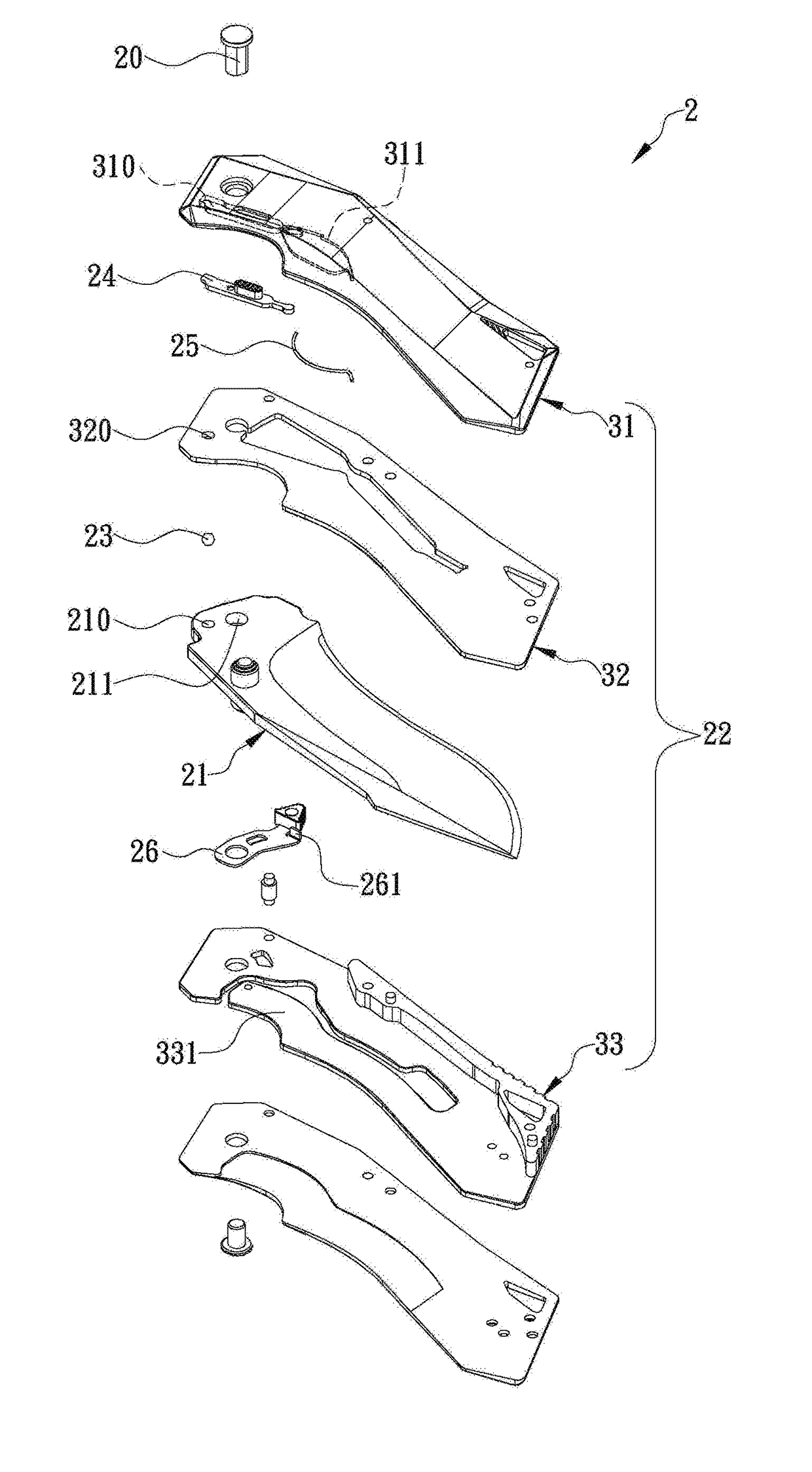
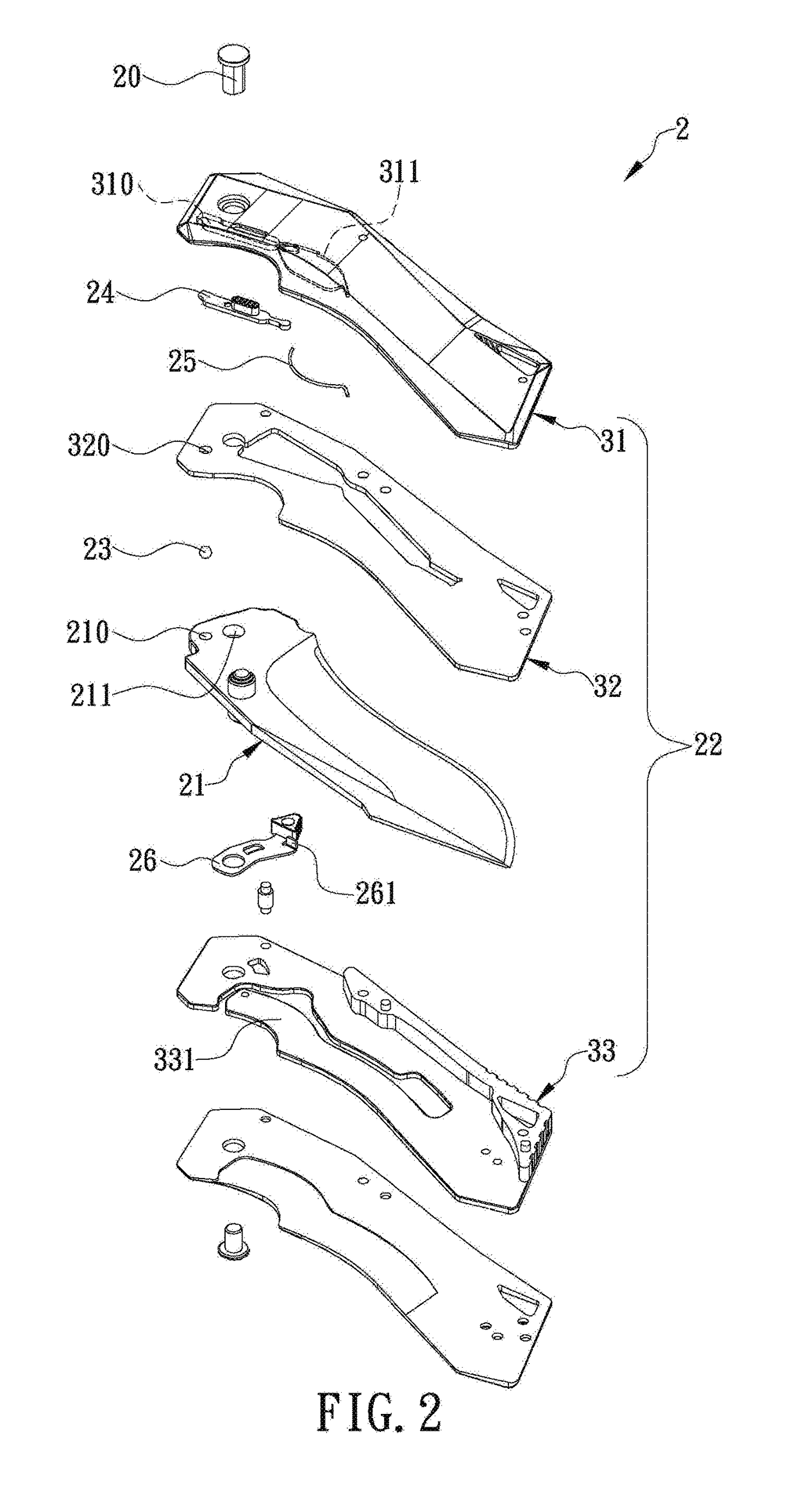
[0013]The present invention provides a knife configured to receive a blade securely and safely. Referring to FIG. 2 for a preferred embodiment of the invention, the knife 2 includes a blade 21, a handle 22, a positioning member 23, and a locking switch 24. One side of the blade 21 is provided with an engaging hole 210 and a pivotal connection hole 211, both adjacent to one end (hereinafter the first end) of the blade 21 (or more particularly the end away from the blade tip). A portion of the blade 21 that is adjacent to the first end of the blade 21 is pivotally provided in a portion in the handle 22 that is adjacent to one end of the handle 22, thanks to a pivot pin 20 (which extends through the pivotal connection hole 211). Thus, the blade 21 can be rotated with respect to the handle 22 about a center defined by the pivot pin 20, allowing the blade tip at the opposite end of the blade 21 to be rotated out of the handle 22 (i.e., to enter an “unfolded state”) or to be received in a...


PUM


Abstract

The present invention is to provide a knife configured to receive a blade securely and safely in a handle thereof. The handle is assembled at least from first to third plates. The blade has one end pivotally connected between the second and third plates. The first plate has a switch groove extending in a front-rear direction and configured to position a locking switch. The second plate has a positioning hole corresponding to the switch groove. A positioning member (e.g., a steel ball) is engaged in the positioning hole. When the blade is received in the handle, an engaging hole in the blade corresponds precisely to the positioning hole so that a user can push the locking switch against a top portion of the positioning member, and consequentially for enabling a bottom portion of the positioning member to extend into the engaging hole, thereby fixing the blade and preventing the blade from exposure.

Description

FIELD OF THE INVENTION[0001]The present invention relates to a knife configured to receive a blade securely and safely. More particularly to a knife whose blade is provided with an engaging hole and whose handle is provided with a switch groove and a positioning hole, wherein the switch groove and the positioning hole are movably engaged with a locking switch and a positioning member respectively such that, when the blade is received in the handle, a top portion and a bottom portion of the positioning hole are in communication with the switch groove and the engaging hole respectively, allowing a user to push the locking switch and consequently a top portion of the positioning member, thereby driving a bottom portion of the positioning member into the engaging hole to fix the blade and prevent the blade from getting loose or exposed outside the handle.BACKGROUND OF THE INVENTION[0002]Recently, with the advancement of craft techniques and the improvement of living standards, people wh...

Claims


Application Information

Patent Timeline
Patent Type & Authority Applications(United States)
IPC IPC(8): B26B1/04
CPCB26B1/048B26B1/044B26B1/046
Inventor LIAO, SHUN-YI
Owner LIAO SHUN YI
Why Eureka
Try Eureka