Al technical title is built by PatSnap Al team. It summarizes the technical point description of the patent document.
a technology of screw driver and torque, applied in the field of punches, can solve the problems of screw driver bit damage screw driver bit application restriction, etc., and achieve the effect of comparatively increasing the driving torqu
Inactive Publication Date: 2006-10-12
LIN CHAO WEI
View PDF9 Cites 5 Cited by
Summary
Abstract
Description
Claims
Application Information
AI Technical Summary
This helps you quickly interpret patents by identifying the three key elements:
Problems solved by technology
Method used
Benefits of technology
[0009] In order to tightly engage a screw driver bit with a drive recess, fan-shaped grooves of the drive recess of the screw head can be replaced with arc-shaped grooves. Also, if the angle between arc-shaped protrusions and square protrusion of the screw driver bit is small and the arc-shaped protrusions and square protrusion of the screw is nearly parallel to central line of the screw, the loose engagement (the drive bit wobbles excessively within the drive recess) can be substantially decreased and the driving torque can be comparatively increased, when compared with Taiwan Patent Publication Number 382306. Furthermore, preferably, the arc-shaped groove can have an arc span which is at least more than a half circle. Thus, the drive recess of the screw head of the present invention includes four symmetrical arc-shaped grooves and a square groove formed at the center of the arc-shaped grooves, wherein preferably the arc-shaped groove can have an arc span which is at least more than a half circle. A bit portion of a punch (mold) for forging the screw and a drive bit of a screw driver bit for matching with the screw, correspondingly include four symmetrical arc-shaped protrusions and a square protrusion formed at the center of the arc-shaped protrusions.
Problems solved by technology
Thus, the application of the screw driver bits is restricted, such that currently other screw driver bits cannot insert into the above-mentioned drive recesses, and the screw cannot generate larger diving torque.
If the loose engagement is large, the drive recess and the drive bit of the screw driver bit will be damaged when a power-driven tool suddenly turns to generate large torque, because the engagement between the drive recess and the screw driver bit is not tight, such that the loose engagement is large and then the drive bit slips out of the drive recess.
However, it is not easy to form four fan-shaped grooves, but is easy to damage the mold so as to substantially increase the cost.
Method used
Image
Click on the blue label to locate the original text in one second.
Reading with bidirectional positioning of images and text.
Examples
Embodiment Construction
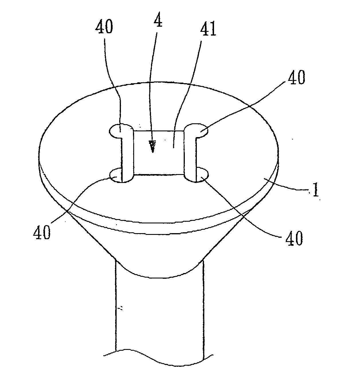
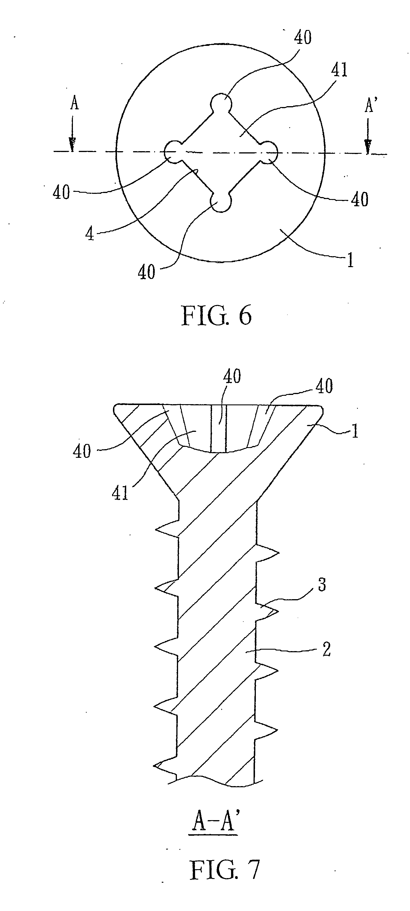
[0026] Referring to FIGS. 6 and 7, they depict a screw according to an embodiment of the present invention. The screw includes a screw head 1, a shank 2 and a male-thread 3. The screw head 1 can be pan head, conical head, circular head, annular head, countersink head, oval head, truss head, etc. The screw head 1 is provided with a drive recess 4, wherein the drive recess 4 includes four symmetrical arc-shaped grooves 40 and a square groove 41 formed at the center of the arc-shaped grooves 40, in order to match with a wide variety of shapes of drive bit of screw driver bit. Also, the arc-shaped groove 40 can be a part of circle-shaped groove or oval-shaped groove. The arc-shaped groove 40 can have an arc span which is at least more than a half circle (e.g. the arc span is three-fourth of circle, shown in FIGS. 6 and 8). Furthermore, an included angle α between groove wall of the arc-shaped groove 40 and central line of the screw is between 0 and 45 degrees, shown in FIG. 9. Likewise,...
PUM
Property
Measurement
Unit
included angle
aaaaa
aaaaa
included angle
aaaaa
aaaaa
driving torque
aaaaa
aaaaa
Abstract
The present invention generally relates to a punch, and more particularly to the improvement of a bit portion of a punch for forging a screw. A drive recess of the screw head includes four symmetrical arc-shaped grooves and a square groove formed at the center of the arc-shaped grooves. Also, the bit portion of the punch is used for forging the screw, and includes four symmetrical arc-shaped protrusions and a square protrusion formed at the center of the arc-shaped protrusions. Thus, the types of slot, cross, cross-square combination, square and double-cross of the drive bit of the conventional screw driver bit can be adapted to insert into and engage with the drive recess. Particularly, when the screw driver bit having arc-shaped drive bit is simultaneously used, it is easy to control the screw during locking and to generate larger driving torque, thereby achieving the object of practical utility and economizing effort.
Description
[0001] This application claims the priority benefit of Taiwan Patent Application Serial Number 094110796, filed Apr. 6, 2005, the full disclosure of which is incorporated herein by reference. BACKGROUND OF THE INVENTION [0002] 1. Field of the Invention [0003] The present invention generally relates to a punch, and more particularly to a punch for forming a drive recess of a screw head, thereby generating larger driving torque. [0004] 2. Description of the Related Art [0005] Currently, conventional screws or bolts include many types of head, such as pan head, conical head, annular head, countersink head, oval head, truss head, etc., which can be adapted to drive recesses such as slot drive recess (A), cross (Phillips) drive recess (B), cross-square combination drive recess (C), square drive recess (D) and double-cross (Pozi) drive recess (E) as respectively shown in FIGS. 1, 2, 3, 4 and 5. However, hand tools which match with the above-mentioned drive recesses (A), (B), (C), (D) and ...
Claims
Application Information
Patent Timeline
Application Date:The date an application was filed.
Publication Date:The date a patent or application was officially published.
First Publication Date:The earliest publication date of a patent with the same application number.
Issue Date:Publication date of the patent grant document.
PCT Entry Date:The Entry date of PCT National Phase.
Estimated Expiry Date:The statutory expiry date of a patent right according to the Patent Law, and it is the longest term of protection that the patent right can achieve without the termination of the patent right due to other reasons(Term extension factor has been taken into account ).
Invalid Date:Actual expiry date is based on effective date or publication date of legal transaction data of invalid patent.
Patent Type & Authority Applications(United States)