Cable connector

Active Publication Date: 2018-02-08
MOLEX INC
View PDF3 Cites 2 Cited by
  • Summary
  • Abstract
  • Description
  • Claims
  • Application Information

AI Technical Summary

Benefits of technology

The cable connector system has a unique design that includes a moveable spring-loaded backshell assembly. This assembly is secured to the cable connector by a spring-loaded latching body that is connected to the main backshell body via guide pins, springs, and shoulder screws. The guide pins provide guidance and alignment for the moveable body, while the springs provide the force to overcome initial mating force and absorb physical tolerances. This results in the cable connector being spring-loaded in the mating direction within the receiving connector. The shoulder screw retains the moveable body to the main backshell body and allows relative movement between the mating portion of the cable connector and the latching portion of the cable connector. Overall, this design provides greater stability and reliability for the cable connection.

Problems solved by technology

With any typical backshell latching connector cable solution, there is always a chance of the cable assembly connector not being fully seated in the receiving connector due to tolerance stack up—accounting for parts normal process variation and clearances between the latching components and corresponding catch point of a mating connector assembly, this results in degradation of SI performance (e.g., Impedance, Return Loss, Xtalk).
In these types of connector assemblies, the complexity and the sheer number of components lead to this tolerance stackup.
Typically, this leads to a loose fit between a plug and receptacle and the consequently and unstable connection.
Examples of this can be un-intention un-mating due to vibration, user error in the sense that the connectors are not fully inserted.

Method used


Image

  • Cable connector
  • Cable connector
  • Cable connector

Examples


Embodiment Construction

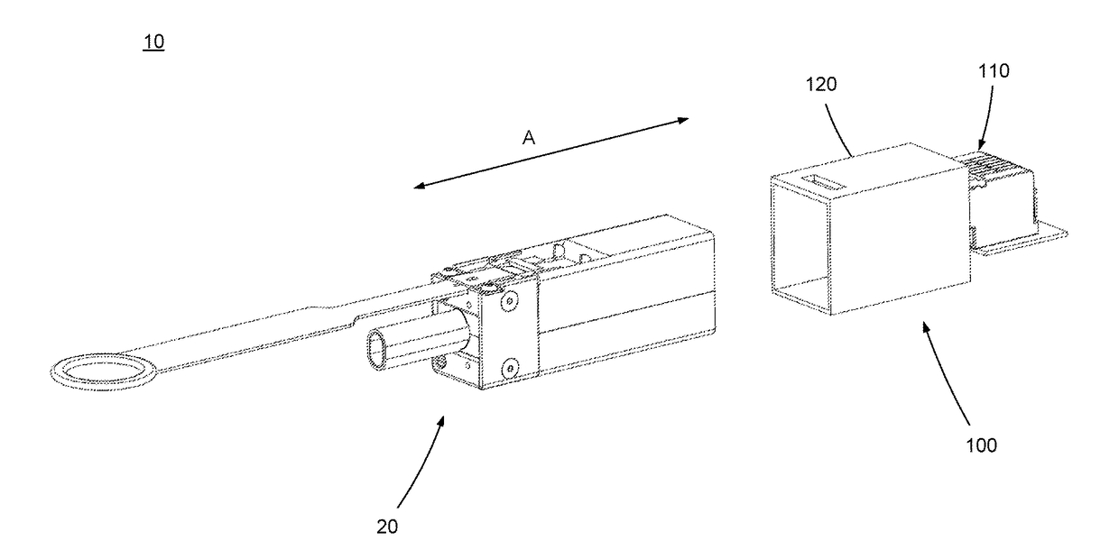
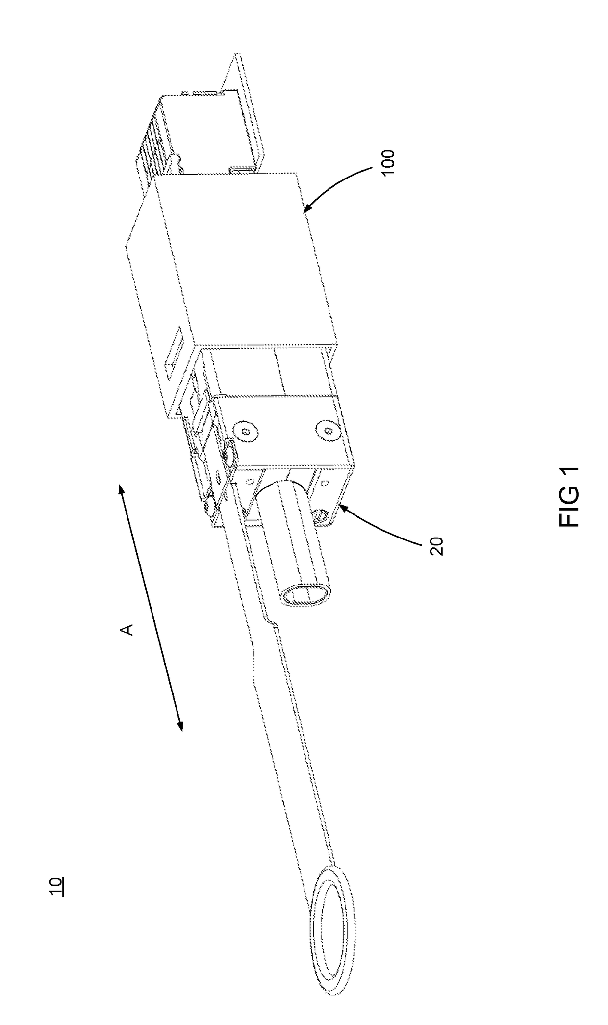
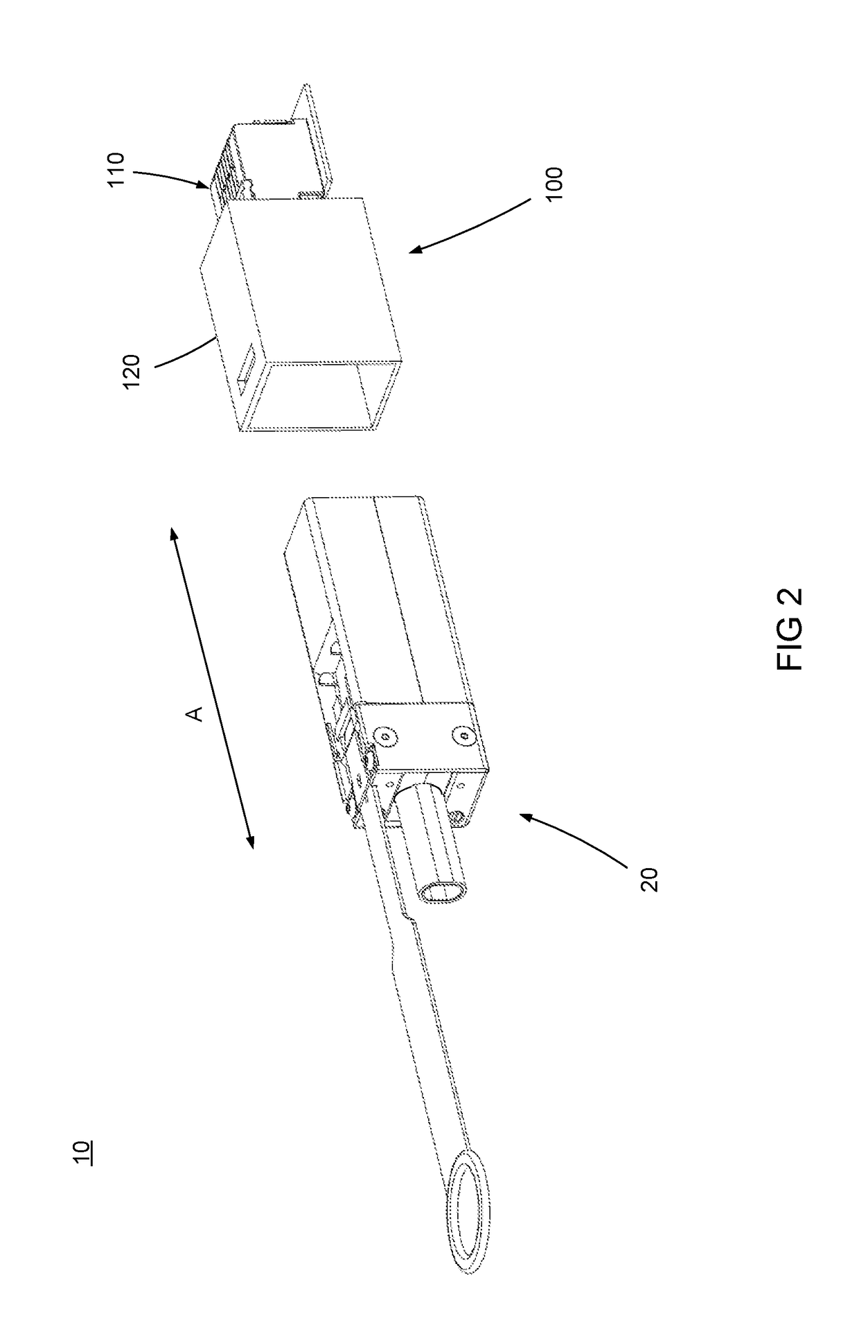
[0016]The appended figures illustrate an embodiment of a cable connector assembly 10 and it is to be understood that the embodiment described and illustrated is merely exemplary of the disclosure, which may be embodied in different forms. Therefore, specific details disclosed herein are not to be interpreted as limiting, but merely as a basis for the claims and as a representative basis for teaching one skilled in the art to variously employ the present disclosure.

[0017]One or more embodiments of the disclosure utilize a modular construction and are typically used in the area of high data rate signal transmission that generally include a cable connector and a backplane connector. The cable connector typically includes a plurality of wafers disposed in a housing with a multi conductor cable conducted to individual terminals within the wafers. The cable connector is configured to be mated to a backplane or to other suitable receptacles that may also include a plurality of wafers with ...


PUM


Abstract

A cable connector assembly includes a first connector configured to mate with a second connector. The first connector has a first housing that supports a wafer with a first mating portion defined by the first housing and the wafer. The first connector includes a cable connected to the wafer that is disposed in a first housing. The first connector also includes a second housing with a latch and the second housing is movably mounted to the first housing. A biasing element disposed between the first housing and the second housing acts to urge the first housing and the second housing apart.

Description

RELATED APPLICATIONS[0001]This application claims priority to U.S. Provisional Application No. 62 / 114,197, filed on Feb. 10, 2015 which is incorporated herein by reference in its entirety.FIELD OF THE INVENTION[0002]The current disclosure is directed to the field of cable connector assemblies and more particularly to a cable connector assembly with a spring-loaded backshell latching body.DESCRIPTION OF RELATED ART[0003]With any typical backshell latching connector cable solution, there is always a chance of the cable assembly connector not being fully seated in the receiving connector due to tolerance stack up—accounting for parts normal process variation and clearances between the latching components and corresponding catch point of a mating connector assembly, this results in degradation of SI performance (e.g., Impedance, Return Loss, Xtalk).[0004]In these types of connector assemblies, the complexity and the sheer number of components lead to this tolerance stackup. Typically, t...

Claims


Application Information

Patent Timeline
IPC IPC(8): H01R13/635H01R13/66G06F1/18H01R13/627H01R13/58H01R13/508
CPCH01R13/635H01R13/5804H01R13/508G06F1/183H01R13/6272H01R13/6658H01R13/6335H01R2107/00H01R13/6275
Inventor RESENDEZ, JAVIERJANOTA, KENNETH
Owner MOLEX INC
Why Eureka
Try Eureka