Lever-type connector

a connector and lever-type technology, applied in the direction of connection, electrical apparatus, coupling device connection, etc., can solve the problems of deterioration of the reliability of the fitting with the mating connector, etc., to achieve high fitting reliability, reduce backlash of the operating portion, and reduce the effect of bending

Active Publication Date: 2018-03-08
YAZAKI CORP
View PDF12 Cites 4 Cited by
  • Summary
  • Abstract
  • Description
  • Claims
  • Application Information

AI Technical Summary

Benefits of technology

[0030]In the lever-type connector having the above configuration, when the lever is moved to the fitting completion position, the recessed portions of the operating portion are externally fitted to the pair of the walls on both sides of the lock portion without any gaps (a state of no gaps or pressurized contact). Therefore, it is possible to further suppress backlash of the operating portion of the lever engaged and locked to the lock portion in the fitting completion position. As a result, even if an external force such as vibration or shock is applied, the lever can be engaged and locked by the lock portion, thus high fitting reliability with the mating connector can be achieved.
[0031]In the lever-type connector of the above configuration, when the lever is placed in the fitting completion position, the backlash-eliminating protrusions protruding from either the outer surfaces of the pair of walls or the inner surfaces of the recessed portions are compressed and deformed in a state where the recessed portions of the operating portion are pressed against the pair of walls. By backlash-eliminating protrusions which are easy to compress and deform, it is possible to easily suppress backlash of the operating portion of the lever engaged and locked to the lock portion in the fitting completion position.
[0032]In the lever-type connector having the above configuration, the locking protrusions on the inner surfaces of the side plates of the lever can lock the lever to the housing in the temporary locking position. Therefore, it is possible to prevent careless rotation of the lever before fitting to the mating connector and eliminate complicated operations in returning the carelessly rotated lever to the temporary locking position, thus, making it possible to smoothly perform the fitting to the mating connector.
[0033]When rotating the lever, by way of the locking projections on the inner surface of the side plates of the lever passing through the escape grooves formed in the side surfaces of the housing, the lever is smoothly pivoted in a predetermined direction without the locking protrusions coming in contact with the side surfaces of the housing. Then, when the lever is moved to the fitting completion position, the locking protrusion of the lever rides on the locking surface of the escape groove and suppresses backlash of the lever. As a result, even if an external force such as vibration or shock is applied, the lever can be engaged and locked by the lock portion more securely, thus high fitting reliability with the mating connector can be achieved.
[0034]In the lever-type connector of the above configuration, when at least the lever is moved to the fitting completion position, the inner surface of the locking piece formed on the support shaft protruding on both sides of the housing presses the pressed protrusion, formed in the vicinity of the pivot hole in the side plate, toward the side of the housing. Therefore, in the side plates of the lever, backlash of the support shaft of the housing is suppressed, and generation of noise from vibrations are prevented.
[0035]According to the present invention, it is possible to provide a lever-type connector that suppresses backlash of a lever and obtains a high fitting reliability with a mating connector.

Problems solved by technology

When an external force such as a vibration or shock is applied to the mating connector, the lever rattles with respect to the housing, and an abnormal noise may be generated or the engagement of the lever by the lock portion of the housing may loosen, and the reliability of the fitting with the mating connector may deteriorate.

Method used


Image

  • Lever-type connector
  • Lever-type connector
  • Lever-type connector

Examples


Embodiment Construction

[0046]Hereinafter, an embodiment of the present invention will be described with reference to the drawings.

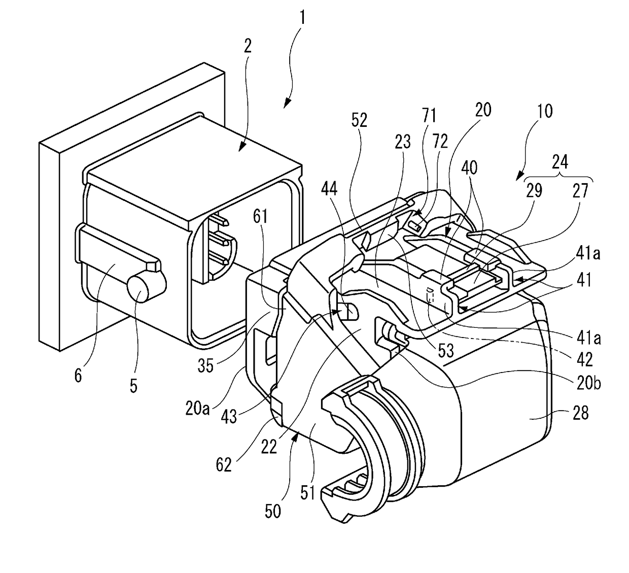
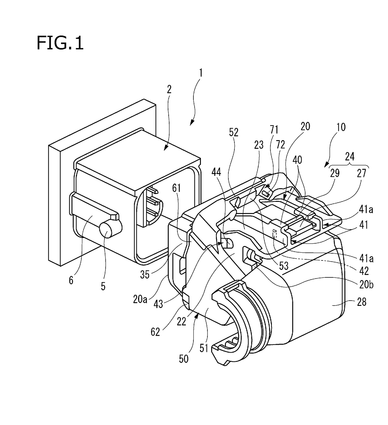
[0047]FIG. 1 is a perspective view of a lever-type connector 10 according to an embodiment of the present invention viewed from the rear before being fitted to a mating connector 1. FIG. 2 is a perspective view of the housing 20 shown in FIG. 1. FIG. 3A illustrates a side view of the housing 20 shown in FIG. 2, and FIG. 3B is a cross sectional view illustrating the inner surface of the side plate 51 of the lever 50 shown in FIG. 1.

[0048]As shown in FIGS. 1 to 3B, the lever-type connector 10 according to the present embodiment includes a housing 20 and a lever 50. The lever-type connector 10 is fitted to the mating connector 1 by fitting the mating housing 2 and the housing 20 to each other. The lever 50 has a pair of side plates 51 arranged along the surface on both sides 22 of the housing 20 and an operating portion 52 connecting the ends of the side plates 51. The lever 50 is...


PUM


Abstract

A lever-type connector includes a housing configured to be inserted and removed from a mating housing of a mating connector and a lever. The lever is pivotally operable between a temporary locking position and a fitting completion position of the lever. The lever includes a pair of side plates and an operating portion. A lock portion is provided on the housing. Lever disengagement prevention portions are provided on both sides of the housing so as to cover at least respective parts of the side plates of the lever positioned at the fitting completion position from outside.

Description

CROSS REFERENCE TO RELATED APPLICATIONS[0001]This application is based on Japanese Patent Application (No. 2016-174969) filed on Sep. 7, 2016, the contents of which are incorporated herein by reference.BACKGROUND OF THE INVENTION1. Field of the Invention[0002]The present invention relates to a lever-type connector.2. Description of the Related Art[0003]Conventionally, a lever-type connector is known that can perform a connector fitting with a low insertion force due to a rotational force by rotating a lever pivotally mounted on a housing so that the connector is fitted to a mating housing of a mating connector (see, for example, JP-A-2012-69415).[0004]In this lever-type connector, the housing is fitted into the mating housing, and thereafter the lever is pivoted from a fitting start position to a fitting completion position, and by engaging and locking to a lock portion of the housing, and thereby the housing maintains a state in which the connector is fitted to the mating housing.[...

Claims


Application Information

Patent Timeline
Patent Type & Authority Applications(United States)
IPC IPC(8): H01R13/639H01R13/502
CPCH01R13/639H01R13/502H01R13/504H01R13/62933H01R13/62938H01R13/62955H01R2107/00
Inventor SHIMIZU, TOMOHIKOSUZUKI, SHOGOKANDA, HIDENORISAITO, MASAYUKIHASEGAWA, TAKUYATERAO, KAZUYA
Owner YAZAKI CORP
Why Eureka
Try Eureka