Lamp holder, backlight device using the same, and display using the same

a technology of backlight device and lamp holder, which is applied in the direction of lighting and heating apparatus, lighting support devices, instruments, etc., can solve the problems of inability to prevent the thickness the clearance between the lamp holding part and the cold cathode tube is too large, and the lamp holding part cannot be set to the size of the cold cathode tube. , to achieve the effect of reducing backlash, reliable attachment and detachability, and maintaining excellen

Inactive Publication Date: 2010-03-16
SHARP KK
View PDF30 Cites 7 Cited by
  • Summary
  • Abstract
  • Description
  • Claims
  • Application Information

AI Technical Summary

Benefits of technology

[0009]In order to overcome the problems described above, preferred embodiments of the present invention suppress backlash while ensuring reliable attaching and detaching operability and maintaining excellent performance.
[0011]With the above constitution, by providing the recessed portion at the opposed surface of the lamp holding part at the position between the end portion and the connecting region connected to the mounting portion, the elastic rebound force which occurs to the lamp holding part at the time of opening deformation is significantly reduced. Accordingly, even if the size of the lamp holding part is set so as to be able to hold a relatively thin lamp without backlash, operability and holding performance on the occasion of attaching and detaching a relatively thick lamp can be kept favorable.
[0012]With a lamp holder according to a preferred embodiment of the present invention, a backlight device using the same, and a display using the same, even if the thickness of lamps varies due to a manufacturing error, backlash of the lamps can be prevented and minimized while maintaining attaching and detaching operability and achieving excellent performance.

Problems solved by technology

Incidentally, typically there is a variation in the thickness of the cold cathode tube that cannot be prevented due to a manufacturing error.
Thus, setting the size of the lamp holding part which holds such a cold cathode tube can be problematic.
If the size of the lamp holding part is set with the thickest cold cathode tube in tolerance as a reference, the clearance which occurs between the lamp holding part and the cold cathode tube becomes too large when a relatively thin cold cathode tube is mounted, and large backlash occurs to the cold cathode tube.
Even if it is mounted, the elastic rebound force of the lamp holding part becomes too large, and therefore, there arises the problem that the cold cathode tube is urged in the detaching direction by the elastic rebound force and the cold cathode tube is easily detached, and in short, this setting method is not favorable with respect to attaching and detaching operability and holding performance.
Nevertheless, there are limitations in the molding technique and strength in molding the lamp holding part to be thin in order to reduce the elastic rebound force of the lamp holding part, thus bringing about difficulties in coping with this situation.

Method used


Image

  • Lamp holder, backlight device using the same, and display using the same
  • Lamp holder, backlight device using the same, and display using the same
  • Lamp holder, backlight device using the same, and display using the same

Examples


Embodiment Construction

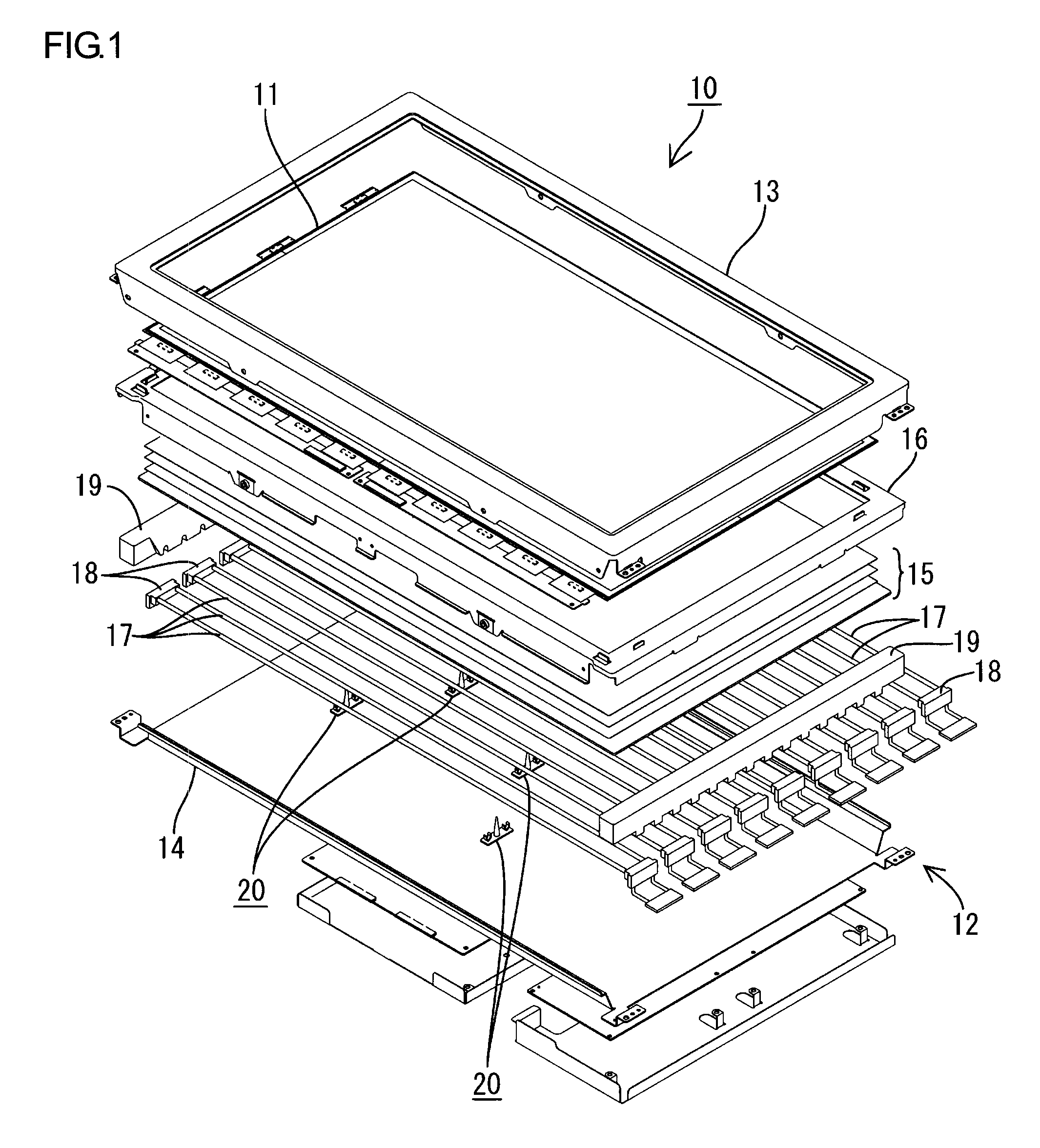
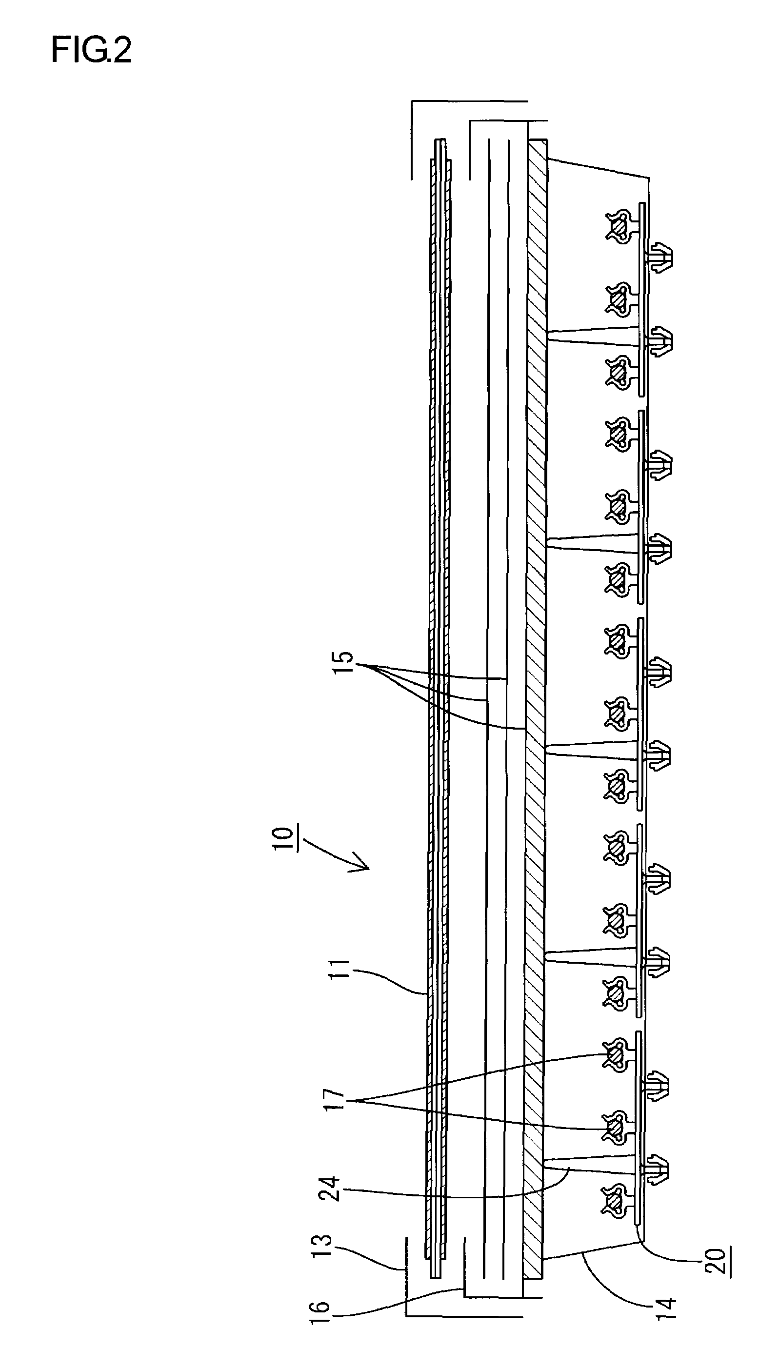
[0029]Preferred embodiments of the present invention will be described based on FIGS. 1 to 11. In the present preferred embodiment, a lamp clip 20 which is used for a backlight device 12 of a liquid crystal display 10 will be shown as an example. In the following description, a vertical direction is described with each of the drawings as a reference, and the lateral direction will be described with FIG. 3 as a reference.

[0030]First, a liquid crystal display 10 will be described. The liquid crystal display 10 broadly includes a liquid crystal panel 11 which preferably has a substantially rectangular shape and the backlight device 12 which is an external light source, and they are integrally held by a bezel 13 or the like, as shown in FIGS. 1 and 2. The liquid crystal panel 11 (which is a display panel) has the construction in which a pair of glass substrates are bonded to each other with a predetermined gap therebetween, and liquid crystal material is sealed between both the glass su...


PUM


Abstract

A lamp holder includes a mounting portion, a lamp holding part which is connected to the mounting portion, and includes an end capable of surrounding a peripheral surface of a lamp, and is capable of being elastically opened and deformed with attaching and detaching of the lamp. The present invention also includes a recessed portion positioned at an opposed surface to the lamp in the lamp holding part and in a position between an end portion and a connecting region to a mounting portion, such that the recessed portion allows the lamp holding part to bend so that the end portion displaces in a direction to be away from the peripheral surface of the lamp.

Description

BACKGROUND OF THE INVENTION[0001]1. Field of the Invention[0002]The present invention relates to a lamp holder, a backlight device using the same, and a display using the same.[0003]2. Description of the Related Art[0004]For example, a liquid crystal panel used for a liquid crystal display such as a liquid crystal television additionally requires a backlight device as an external lamp because it does not spontaneously emit light. The backlight device is placed on a backside of the liquid crystal panel, and broadly includes a base made of a metal with an open surface at the side of the liquid crystal panel, a number of cold cathode tubes housed in the base as lamps, and a number of optical members (diffusion sheets and the like) which are arranged in an open portion of the base to efficiently irradiate light, which is emitted by the cold cathode tubes, to the liquid crystal panel side, and includes lamp clips for holding the cold cathode tubes, each having a slim tubular shape with r...

Claims


Application Information

Patent Timeline
Patent Type & Authority Patents(United States)
IPC IPC(8): F21V21/00
CPCF21V19/009G02F1/133604G02F1/133608
Inventor TAKATA, YOSHIKIKUDARI, TATSUYA
Owner SHARP KK
Why Eureka
Try Eureka