Drive mechanism for movable mirror of camera

a technology of drive mechanism and mirror, which is applied in the direction of optics, exposure control, instruments, etc., can solve the problems of image shake, inability to effectively control the vibration of the sub-mirror, and disturb the improvement of continuous shooting speed, so as to achieve the effect of simple structure and reliable control of the sub-mirror bouncing

Active Publication Date: 2015-01-08
RICOH IMAGING COMPANY
View PDF1 Cites 7 Cited by
  • Summary
  • Abstract
  • Description
  • Claims
  • Application Information

AI Technical Summary

Benefits of technology

[0007]The present invention has been devised with consideration of the above described problems and provides a movab

Problems solved by technology

Upon the movable mirror rotating and bouncing (vibrating) upon impact against a positioning memer, vibrations of the movable mirror can cause image shake and disturb improvement in continuous shooting speed.
In addition, if the sub-mirror bounces to thereby cause mechanical shock upon the main mirror rotating to the retracted position, this shock (mirror shock) becomes a cause of camera shake (image shake), so that it is r

Method used


Image

  • Drive mechanism for movable mirror of camera
  • Drive mechanism for movable mirror of camera
  • Drive mechanism for movable mirror of camera

Examples


Embodiment Construction

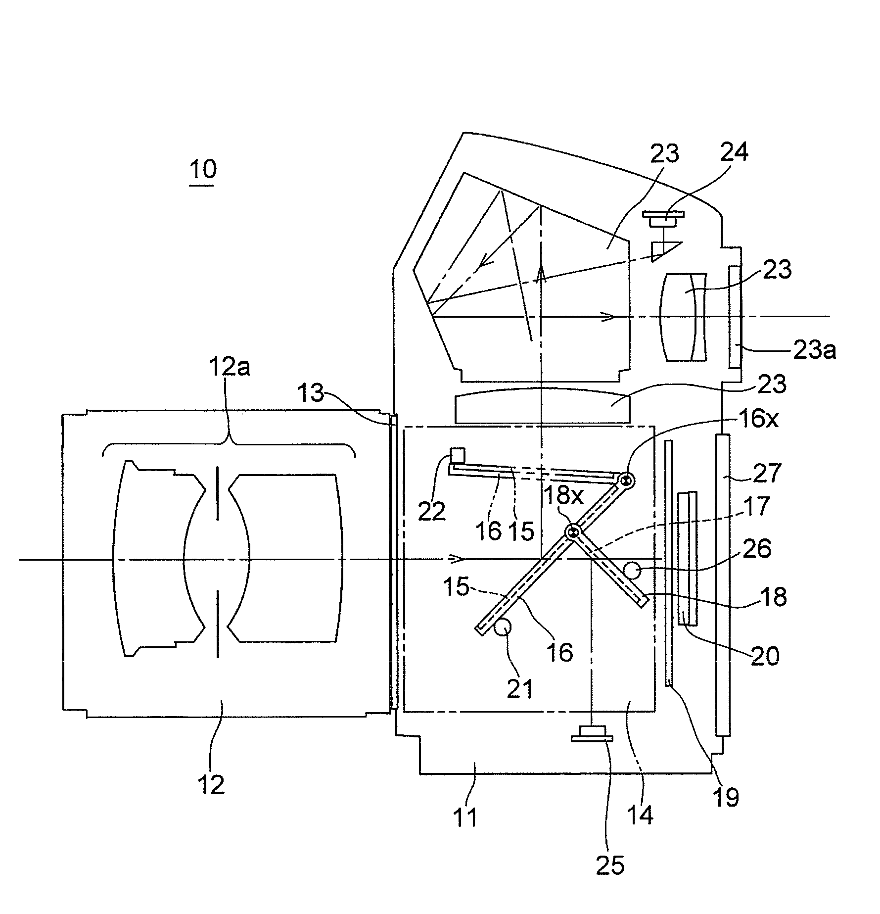
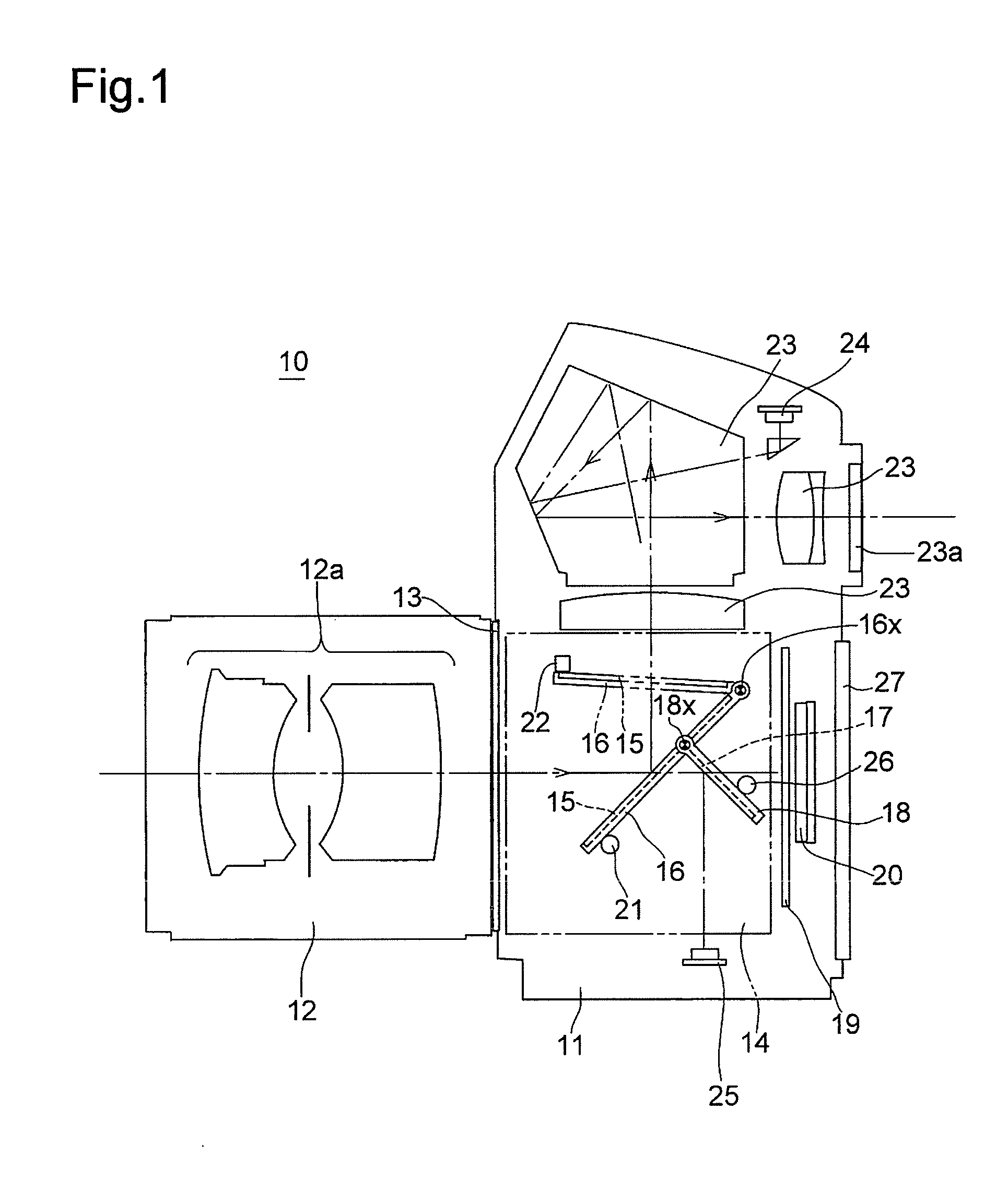
[0044]An SLR camera (hereinafter referred simply to as camera) 10 shown in FIG. 1 is provided on the front of a camera body 11 with a lens mount 13, to which an interchangeable lens 12 is detachably attached. The camera body 11 is provided therein behind the lens mount 13 with a mirror box 14.

[0045]The camera body 11 is provided, inside the mirror box 14, with a main mirror 15 and a sub-mirror 17 which constitute a movable mirror (quick-return mirror). The main mirror 15 is fixedly supported on a main mirror seat (main-mirror holding frame) 16, and the main mirror seat 16 is installed between both side walls of the mirror box 14 and is pivoted about a pair of main-mirror support shafts 16x coaxial with each other which are respectively fixed to these side walls. The movable mirror is provided, on the main mirror seat 16, with a sub-mirror seat (sub-mirror holding frame) 18 which is pivoted on the main mirror seat 16 about a pair of sub-mirror support shafts 18x coaxial with each oth...


PUM


Abstract

A movable-mirror drive mechanism of a camera includes a main mirror held by a main-mirror holding frame rotatable between a viewfinder light-guiding position and a retracted position; a sub-mirror held by a sub-mirror holding frame that is rotatably supported by the main-mirror holding frame, wherein the sub-mirror holding frame is positioned in a jutting-out position when the main mirror is in the viewfinder light-guiding position, and the sub-mirror holding frame is retracted with the main mirror when the main mirror is in the retracted position; and a vibration control member which rotates in association with rotation of the main-mirror holding frame and holds the sub-mirror holding frame in the jutting-out position to prevent the sub-mirror holding frame from rotating toward the sub-mirror retracted position when the main mirror rotates to the viewfinder light-guiding position.

Description

BACKGROUND OF THE INVENTION[0001]1. Field of the Invention[0002]The present invention relates to a drive mechanism for driving a movable mirror provided in a camera (e.g., an SLR camera), and in particular to a mechanism, provided in association with the drive mechanism, for suppressing bouncing of the movable mirror.[0003]2. Description of the Related Art[0004]In SLR cameras, a movable mirror (quick-return mirror) is provided, which is capable of moving up and down. More specifically, capable of rotating between a viewfinder light-guiding position (mirror-down position), in which the movable mirror is positioned in a photographing optical path to reflect incident light emanated from an object (object-emanated light) toward a viewfinder optical system, and a retracted position (mirror-up position), in which the movable mirror is retracted from the photographing optical path to allow the object-emanated light to travel toward a shutter. In SLR cameras which determine whether an objec...

Claims


Application Information

Patent Timeline
IPC IPC(8): G03B19/12
CPCG03B19/12G03B7/09971G03B2217/002
Inventor SANADA, SHINICHIRO
Owner RICOH IMAGING COMPANY
Why Eureka
Try Eureka