Fuel injection valve

a fuel injection valve and internal combustion engine technology, applied in the direction of fuel injection apparatus, fuel feed system, engine components, etc., can solve the problems of large increase in the number of components and processes, inability to accurately control the amount of fuel injection, and travel members that bounce, so as to improve the accuracy of the linearity of the injection amount and the accuracy of the injection amount.

Inactive Publication Date: 2014-10-14
MITSUBISHI ELECTRIC CORP
View PDF21 Cites 7 Cited by
  • Summary
  • Abstract
  • Description
  • Claims
  • Application Information

AI Technical Summary

Benefits of technology

[0012]A fuel injection valve according to the present invention has been implemented in order to solve the foregoing problems; the objective thereof is to realize the structure, of a fuel injection valve, in which, without increasing the number of components and the number of processes, bouncing of the needle can be suppressed and the armature position can be fixed while the valve is closed, and thereby to raise the accuracy of the linearity of an injection amount and the accuracy of an injection amount.
[0013]A fuel injection valve according to the present invention is provided with an armature that is repelled or attracted by a core, by de-energizing or energizing a coil; a needle that opens or closes a valve seat in accordance with a reciprocal travel of the armature; and a valve-closing spring that biases the needle so as to close the valve, when the coil is de-energized. The valve-closing spring is disposed on the armature, and the needle and the armature are fixed in such a way that the armature can travel in an axis direction by a predetermined amount with respect to the needle.
[0014]According to the present invention, an effect is demonstrated in which the responsiveness at the time when the valve is opened can be raised, and bouncing of the needle at the time when the valve is opened can be suppressed with a simple structure, without increasing the number of components.

Problems solved by technology

The vertical movement causes the armature to collide with the core 4 or causes the needle 8 to collide with the valve seat 15; as a result, the impact of the collision causes the travel members to bounce, whereby the amount of fuel injection cannot accurately be controlled.
However, there has been a problem that the number of components and the number of processes considerably increase in such a structure, as disclosed in National Publication of International Patent Application No. 2002-506502, in which the armature 7 and the needle 8 are coupled with each other by means of the elastic member 17 such as a spring, whereby the structure becomes complex.
No. 2006-17101, due to the existence of the gap between the stepped portion 19 of the needle 8 and the bottom end 21 of the armature 7, the position of the armature 7 cannot be fixed; therefore, there has been a problem that the vibration of the internal combustion engine or the like causes the distance between the armature 7 and the core 4 to be unstable while the valve is closed, whereby the time required to open the valve fluctuates and the accuracy of an injection amount is deteriorated.

Method used


Image

  • Fuel injection valve
  • Fuel injection valve
  • Fuel injection valve

Examples


embodiment 1

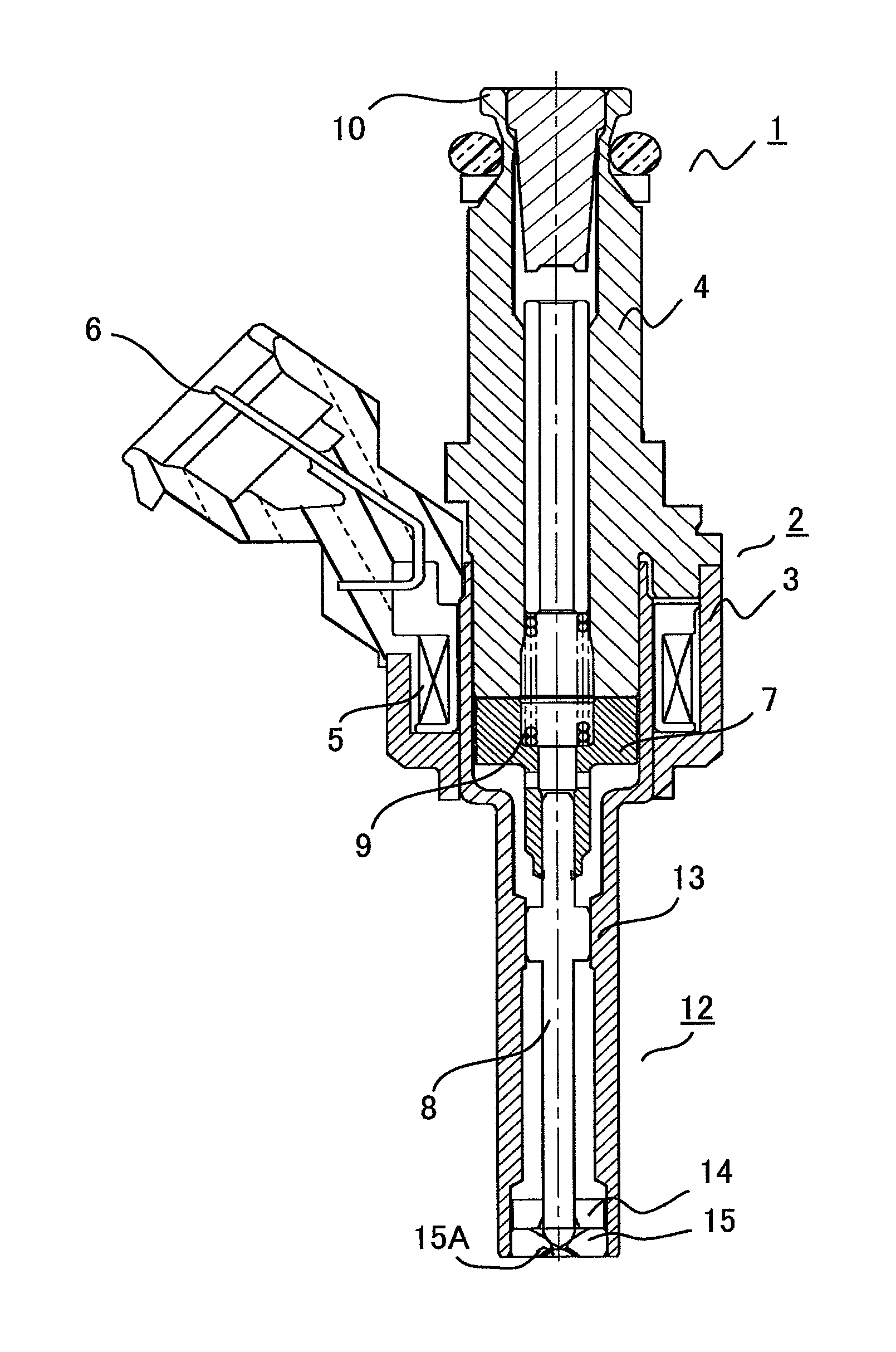
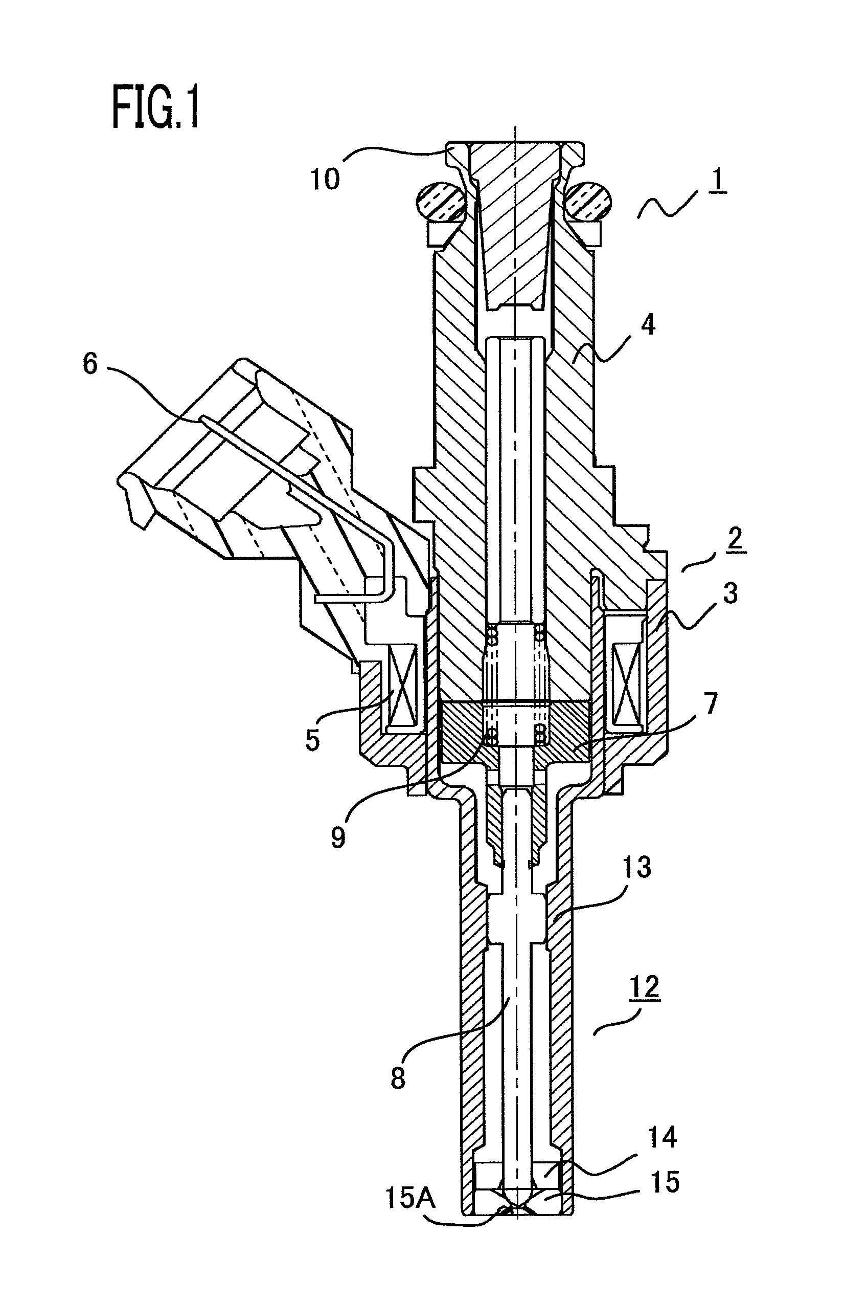
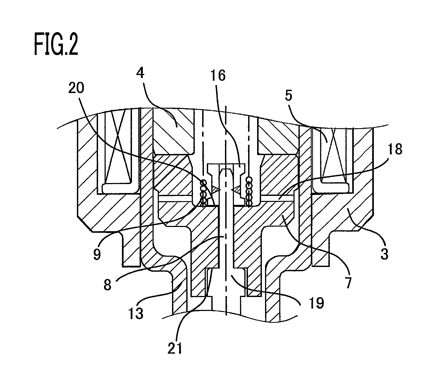
[0023]Embodiment 1 of the present invention will be explained below. FIG. 2 illustrates the detail of the configuration of a fuel injection valve 1 according to Embodiment 1, while partially enlarging a solenoid device 2 and a valve device 12. In FIG. 2, a stepped portion 19 is provided on the side surface of a needle 8, an armature 7 is put on the upstream side of the stepped portion 19 in such a way as to be penetrated by the needle 8, and the front end of the needle 8 is fixed in a stopper 16 by means of welding or the like; on that occasion, the front end of the needle 8 is press-fitted and welded in the stopper 16, while adjusting the stopper 16 in such a way that the armature 7 can travel by a predetermined amount with respect to the needle 8. Additionally, by making a valve-closing spring 9 make contact with the top end 20 of the armature 7, the armature 7 and, eventually, the needle 8 are pressed downstream so that the needle and a valve seat 15 perform a valve-closing opera...

embodiment 2

[0029]In a direct-injection internal combustion engine, in order to expand the injection range or to atomize the spray, the injection fuel is pressurized. Due to the fuel pressure caused by the pressurization, a force exerted on the needle 8 is enlarged; therefore, there has been a problem that, when the needle 8 is seated in the valve seat 15, the collision load increases and thereby the needle 8 and the seating surface of the valve seat 15 wear out, whereby the durability is deteriorated.

[0030]In order to cope with the foregoing problem, the fuel injection valve is configured in such a way as to have the relation given by Equation (1) below in a time period during which the needle 8 starts valve closing and then is seated in the valve seat 15, so that the needle 8 has a valve-opening speed faster than that of the armature 7, and as illustrated in FIG. 3(d), the needle 8 is seated in the valve seat 15, with the armature 7 and the needle 8 left in contact with each other at the upst...

embodiment 3

[0038]FIG. 4 illustrates the detail of the configuration of a fuel injection valve 1 according to Embodiment 3. In FIG. 4, FIG. 4(b) is a cross-sectional view taken along the line A-A in the FIG. 4(a) Embodiment 2 differs from Embodiment 1 only in the method of fixing the needle 8 and the armature 7. That is to say, in FIG. 2, the stepped portion 19 is provided on the side surface of the needle 8, the armature 7 is put on the upstream side of the stepped portion 19 in such a way as to be penetrated by the needle 8, and the front end of the needle 8 is fixed in the stopper 16 by means of welding or the like; however, in FIG. 4, the fuel injection valve has a structure in which, in the side surface of the needle 8, there is provided a groove 22 whose top and bottom end surfaces make contact with the top end surface 20 and the bottom end surface 21, respectively, of the armature 7, the armature 7 is shaped in such a way as to have a slit 23 (refer to FIG. 4(b)) in a portion thereof, an...


PUM


Abstract

The objective of the present invention is to realize the structure, of a fuel injection valve, in which bouncing of the needle can be suppressed and the armature position can be fixed while the valve is closed, without increasing the number of components and the number of processes. In a fuel injection valve including an armature that is repelled or attracted by a core, by de-energizing or energizing a coil, a needle that opens or closes a valve seat in accordance with a reciprocal travel of the armature, and a valve-closing spring that biases the needle so as to close the valve, when the coil is de-energized, the valve-closing spring is disposed on the armature, and the needle and the armature are fixed in such a way that the armature can travel in an axis direction by a predetermined amount with respect to the needle.

Description

BACKGROUND OF THE INVENTION[0001]1. Field of the Invention[0002]The present invention relates to a fuel injection valve for an internal combustion engine and particularly to improvement of an electromagnetic fuel injection valve utilized in a fuel supply system in an internal combustion engine.[0003]2. Description of the Related Art[0004]The typical configuration of a fuel injection valve of this kind will be explained with reference to FIG. 1. As illustrated in FIG. 1, a fuel injection valve 1 is configured mainly with a solenoid device 2 and a valve device 12. The solenoid device 2 is configured with a housing 3 that is a yoke portion of a magnetic circuit, a core 4 that is a fixed iron core portion of the magnetic circuit, a coil 5 energized from outside via a connector 6, an armature 7 that is a moving iron core portion of the magnetic circuit, and a valve-closing spring 9 that biases a needle 8 coupled with the armature 7 downstream. In addition, a fuel is supplied through a fu...

Claims


Application Information

Patent Timeline
Patent Type & Authority Patents(United States)
IPC IPC(8): B05B1/30F02M51/06
CPCF02M51/0685F02M51/0671
Inventor SHINGU, AKIOAOTA, MASAYUKIMUNEZANE, TSUYOSHI
Owner MITSUBISHI ELECTRIC CORP
Why Eureka
Try Eureka