X-ray tube and a controller thereof

a controller and x-ray tube technology, applied in the field of x-ray tubes, can solve the problems of difficult to maintain a correct x-ray generation position, disadvantageous complicating etc., to improve the vacuum holding property/heat radiation property, simplify and enlarge the structure, and eliminate the effect of rotation lubricity measures

Active Publication Date: 2018-03-15
NANO X IMAGING LTD
View PDF72 Cites 1 Cited by
  • Summary
  • Abstract
  • Description
  • Claims
  • Application Information

AI Technical Summary

Problems solved by technology

However, in the configuration of FIG. 7, the cathode 202 is fixed to the center of the rotary shaft of the vacuum vessel 205, so that it is necessary to provide a strong magnetic deflection coil 206 outside the rotating vacuum vessel 205 in order to curve the electron beam 203 emitted from the cathode 202 toward the circumference of the anode 201, which may disadvantageously complicate and enlarge the structure.
Further, it is difficult to maintain a correct X-ray generation position.

Method used


Image

  • X-ray tube and a controller thereof
  • X-ray tube and a controller thereof
  • X-ray tube and a controller thereof

Examples


first embodiment

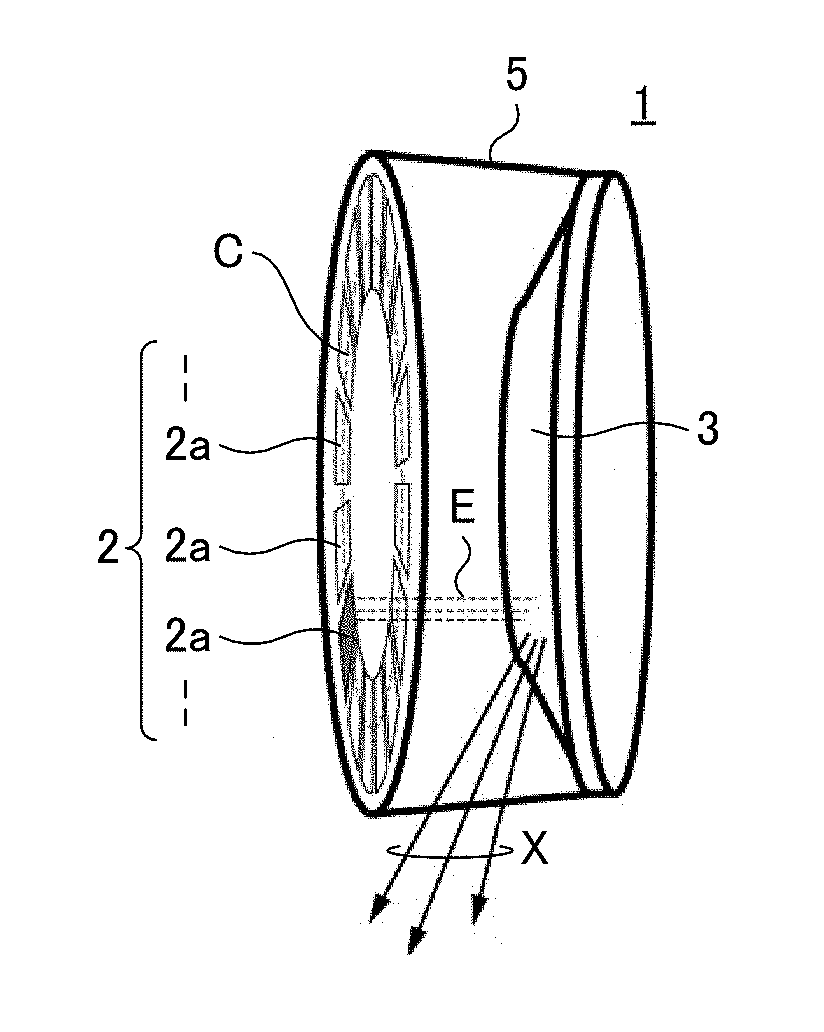
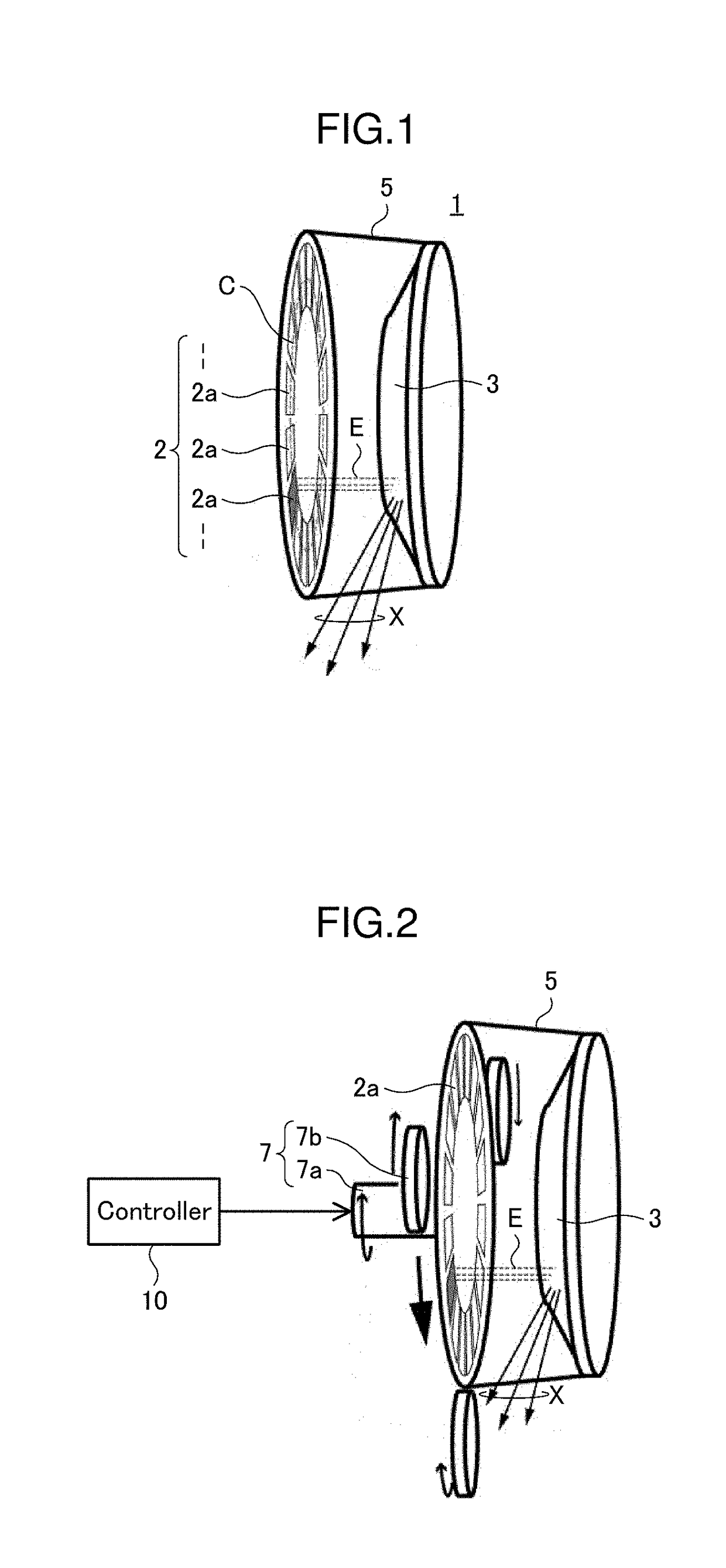
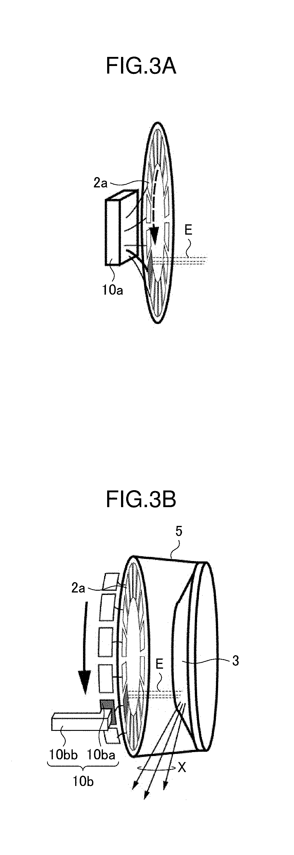
[0022]FIG. 1 is a perspective view schematically illustrating a part of an X-ray tube 1 according to a first embodiment of the present invention, and FIG. 2 is a view illustrating the X-ray tube 1 and a controller 10 according to the first embodiment. As illustrated in FIGS. 1 and 2, the X-ray tube 1 according to the first embodiment of the present invention includes a cathode 2, an anode 3, a vacuum vessel 5, and a rotary mechanism 7.

[0023]The cathode 2 is constituted of a plurality of cathode parts 2a. The plurality of cathode parts 2a are configured as a plurality of parts which are different one another and disposed at equal intervals on a circumference C with the rotary shaft of the rotary mechanism 7 as its center. Further, the cathode parts 2a can individually be turned ON / OFF by the controller 10. A case where a certain cathode part 2a is ON means a state where a voltage having a predetermined value is applied to the cathode part 2a by the controller 10. The cathode part 2a ...

second embodiment

[0037]FIG. 5 is a perspective view schematically illustrating a part of the X-ray tube 1 according to a second embodiment. Although not illustrated in FIG. 5, like the X-ray tube 1 of the first embodiment, the X-ray tube 1 according to the second embodiment includes the vacuum vessel 5, anode 3, and rotary mechanism 7. The X-ray tube 1 according to the present embodiment differs from the X-ray tube 1 according to the first embodiment in that an electrostatic deflection mechanism 8 is additionally provided. Hereinafter, description will be made focusing differences from the first embodiment with the same reference numerals given to the same elements as in the first embodiment.

[0038]The electrostatic deflection mechanism 8 is a doughnut-shaped member disposed between the cathode 2 and the anode 3 and is fixed in the vacuum vessel 5 through the cathode 2. The electrostatic deflection mechanism 8 has a plurality of openings 8a one-to-one corresponding to the plurality of cathode parts 2...


PUM


Abstract

An X-ray tube comprises a vacuum vessel; a cathode and an anode fixedly disposed inside the vacuum vessel; and a rotary mechanism that rotates the vacuum vessel. The cathode is disposed on the circumference with the rotary shaft of the rotary mechanism as its center and includes a plurality of cathode parts that can individually be turned ON / OFF. The anode includes parts opposite to the plurality of cathode parts, respectively.

Description

FIELD OF THE INVENTION[0001]The present invention relates to an X-ray tube and a controller therefor.DESCRIPTION OF RELATED ART[0002]X-ray tubes used in fluoroscopic photographing for medical or other purposes has a cathode and an anode opposite to the cathode in a vacuum vessel and generates an X-ray from an electron colliding portion on the anode by that cathode electrons collide with the anode. Such X-ray tubes are required to generate X-ray having energy and dose sufficiently high enough to transmit a photogenic subject and to have a sufficiently small X-ray generation portion so as to ensure fineness of a fluoroscopic image necessary for the applications. Thus, energy per unit area produced by cathode electrons at the X-ray generation portion, i.e., electron colliding portion may become large enough to melt the anode which is generally made of metal such as tungsten in a moment, which may break the X-ray tube.[0003]As one of methods for solving the above problem, the following ...

Claims


Application Information

Patent Timeline
Patent Type & Authority Applications(United States)
IPC IPC(8): H01J35/06H01J35/08H01J35/14H01J35/16
CPCH01J35/06H01J35/08H01J35/14H01J35/16H01J2235/066H01J2235/068H01J2235/162H01J35/305H01J35/112H01J35/153H01J35/24H01J35/26H01J35/10H01J35/101H01J35/30H01J2235/08H01J2235/06H01J2235/086H01J2235/064H01J2235/10H01J2235/161H01J2235/16H01J35/064
Inventor KENMOTSU, HIDENORIMASUYA, HITOSHI
Owner NANO X IMAGING LTD
Why Eureka
Try Eureka