Method for producing laminated electrode assembly

Active Publication Date: 2018-04-26
TOYOTA JIDOSHA KK
View PDF8 Cites 0 Cited by
  • Summary
  • Abstract
  • Description
  • Claims
  • Application Information

AI Technical Summary

Benefits of technology

The patent describes a method for producing a stable and restrained laminated electrode assembly for use in batteries. The method involves using a heat shrinkable film to restrain the assembly and prevent damage to the bonded area between the tape and the outermost layer during operation. The use of the film also improves the impregnation and release properties of the battery, as well as gas release during abnormal situations. The method is simple and efficient, making it ideal for use in battery production.

Problems solved by technology

However, in the case of preventing the lamination displacement by using the tape, breakage (particularly, peeling of the active material layer in the bonded portion between the tape and the active material layer) may occur at the bonded portion between the tape and the outermost layer (for example, electrode, separator) of the laminated electrode assembly, and the tape may be peeled off during the operation.

Method used


Image

  • Method for producing laminated electrode assembly
  • Method for producing laminated electrode assembly
  • Method for producing laminated electrode assembly

Examples


example 1

Variation Example 1

[0068]In Variation Example 1, as shown in FIG. 6A, a heat shrinkable film 50A has cutout portions 52A. As shown in FIG. 6B, in the enveloping step S102, the cutout portions 52A are arranged on the end faces 14 parallel to the lamination direction of the laminate 10.

[0069]Specifically, a cutout portion is provided in the center of a portion of the heat shrinkable film 50A to be disposed on each of the pair of end faces 14 of the laminate.

[0070]After carrying out the above-described laminate preparation step S101, in the enveloping step S102, the cutout portions 52A of the heat shrinkable film 50A are disposed on the end faces 14 parallel to the lamination direction of the laminate 10. The laminated electrode assembly 100A can then be produced by carrying out the heating step S103.

[0071]As shown in FIG. 6C, in the laminated electrode assembly 100A which has thus been produced, a pair of end faces 16 of the laminate 10 which is not enveloped by the heat shrinkable fi...

example 2

Variation Example 2

[0074]In Variation Example 2, as shown in FIG. 7A, a heat shrinkable film 50B has two cutout portions 52B. Further, as shown in FIG. 7B, a laminate 10B has current collecting tabs 18B of electrodes (positive electrode and negative electrode) on an end face 14B parallel to the lamination direction.

[0075]After carrying out the above-described laminate preparation step S101, as shown in FIG. 7C, in the enveloping step S102, the cutout portions 52B are disposed on the end face 14B parallel to the lamination direction of the laminate 10B so that the current collecting tabs 18B of the laminate 10B protrude from the heat shrinkable film 50B. Then, a laminated electrode assembly can be prepared by carrying out the above-described heating step S103.

[0076]Thus, the number, size, and positions of the cutout portions are not particularly limited, as long as the laminated electrode assembly can be stably restrained, and can be appropriately set according to the design of the l...

example 3

Variation Example 3

[0078]In Variation Example 3, as shown in FIG. 8, a sheet-like heat shrinkable film 50C is used.

[0079]After carrying out the above-described laminate preparation step S101, as shown in FIG. 8, in the enveloping step S102, the heat shrinkable film 50C is wound around the laminate 10, and the pair of main faces 12 and the pair of end faces 14 of the laminate 10 are enveloped by the heat shrinkable sheet (film) 50C. The winding can be easily performed, for example, by folding the heat shrinkable sheet (film) 50C so as to enclose the laminate 10C, and fixing one end portion and the other end portion of the heat shrinkable film 50C on the one main face 12 of the laminate 10 with a pressure-sensitive adhesive tape 70. Then, a laminated electrode assembly can be prepared by carrying out the above-described heating step S103.

[0080]In Variation Example 3, the operation of enveloping the four faces of the laminate 10C with the heat shrinkable film 50C is greatly facilitated...


PUM


Abstract

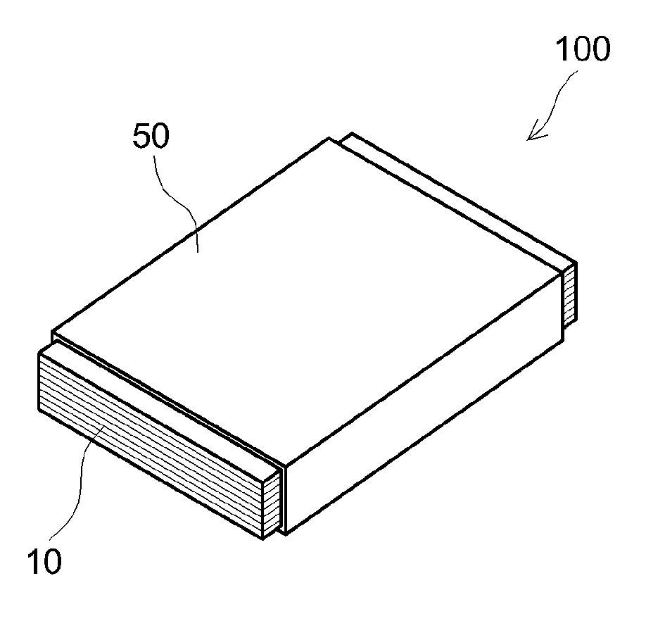
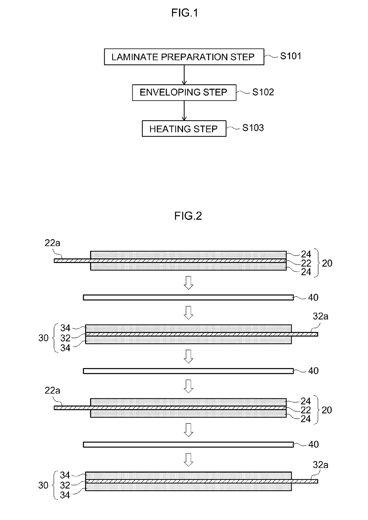
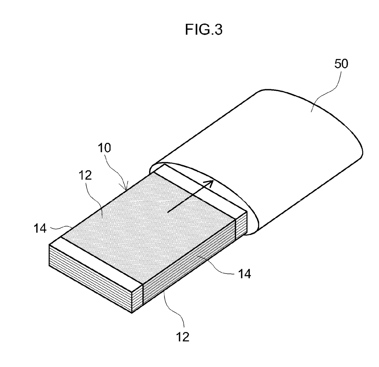
Provided is a method capable of producing, with excellent operability, a laminated electrode assembly which is stably restrained. The method for producing a laminated electrode assembly disclosed herein includes a step of preparing a laminate in which a plurality of positive electrode sheets and a plurality of negative electrode sheets are alternately laminated, and a separator is interposed between each positive electrode sheet and each negative electrode sheet; a step of enveloping, with a heat shrinkable film, four faces of the laminate including a pair of main faces perpendicular to a lamination direction of the laminate and facing each other, and a pair of end faces parallel to the lamination direction of the laminate and facing each other; and a step of heating the pair of end faces while sandwiching the pair of main faces with a cooling plate to thermally shrink the heat shrinkable film on the pair of end faces.

Description

BACKGROUND OF THE INVENTION1. Field of the Invention[0001]The present teaching relates to a method for producing a laminated electrode assembly. The present application claims priority based on Japanese Patent Application No. 2016-208597 filed on Oct. 25, 2016, the entire contents of which are incorporated herein by reference.2. Description of the Related Art[0002]Since nonaqueous electrolyte secondary batteries such as lithium ion secondary batteries (lithium secondary batteries) are lighter in weight and higher in energy density than existing batteries, nonaqueous electrolyte secondary batteries have recently been put to use as the so-called portable power supplies for personal computers, portable terminals, etc. and also as drive power supplies for vehicles. In particular, lithium ion secondary batteries that are lightweight and can produce a high energy density are expected to be more and more popular as high-output power supplies for driving vehicles such as electric vehicles (...

Claims


Application Information

Patent Timeline
IPC IPC(8): H01M10/04H01M2/02B32B37/06
CPCH01M10/0468H01M2/0275B32B37/06H01M2002/0297B32B2457/10H01M2220/20H01M10/0585H01M10/0463H01M10/0525Y02E60/10Y02P70/50H01M50/171H01M10/0436H01M10/0413H01M10/052H01M50/116H01M50/131H01M50/166
Inventor MATSUMOTO, MIZUHO
Owner TOYOTA JIDOSHA KK
Why Eureka
Try Eureka