
Finger stop with integrated sling swivel

a technology of sling swivel and finger stop, which is applied in the field of finger stop technology for integrating sling swivel onto firearms, can solve the problems of affecting the type of sling swivel on the rifle, the risk of the weapon becoming entangled with other objects such as clothing or other objects, and the multitude of parts attached or hanging from the rail, so as to reduce clutter and protuberances, facilitate the securement of the weapon, and minimize the clutter of the weapon protub

Inactive Publication Date: 2018-05-03
KOLB JOHN CLIFFORD +2
View PDF3 Cites 2 Cited by
  • Summary
  • Abstract
  • Description
  • Claims
  • Application Information

AI Technical Summary

Benefits of technology

The patent describes a finger stop that can be attached to a weapon's rail system. The finger stop reduces clutter and improves the weapon's handling and smoothness of operation. It also helps increase muscle memory and reduces hand fatigue. The finger stop is securely locked into position using a spring actuated ball mechanism and a lip or raised sling swivel adapter. Additionally, the patent describes a lip or raised sling swivel adapter that extends from the weapon's cylinder for securing the sling swivel mechanism. Overall, the finger stop and the related attachment system improve the user experience and performance of the weapon.

Problems solved by technology

When a rifle is to be used, the type of sling swivel on the rifle can be critical.
Such arrangements can easily result in a multitude of parts attached or hanging from the rail.
When multiple items are attached to a weapon's rail, the risk that the weapon might become entangles on other objects such as clothing or other gear when the weapon is unslung or otherwise moved into a position of use.
Such tangles when freeing or shouldering the weapon increase the likelihood of a negligent discharge as a user will often, when a weapon is entangled, pull at or jostle the weapon to free it.
Also, if a user is fatigued or otherwise experiences physical difficulty, or if a given sling system is difficult to figure out or use, this can also increase the risk of a negligent discharge, or simply slow down the employment of the weapon.
Currently some products allow a hand rest or finger rest but do not integrate a sling swivel attachment point into the finger rest.
This results in the addition of another apparatus to attach the sling, therefore cluttering the weapons rail system, which as discussed, can be a critical disadvantage.

Method used


Image

  • Finger stop with integrated sling swivel
  • Finger stop with integrated sling swivel
  • Finger stop with integrated sling swivel

Examples


Embodiment Construction

[0066]Other objects, features and advantages of the invention will become apparent from a consideration of the following detailed description and the accompanying drawings. The following descriptions are made referring to the figures, wherein like reference numbers refer to like features throughout this description. Not all numbers appearing in one figure are necessarily present in another.

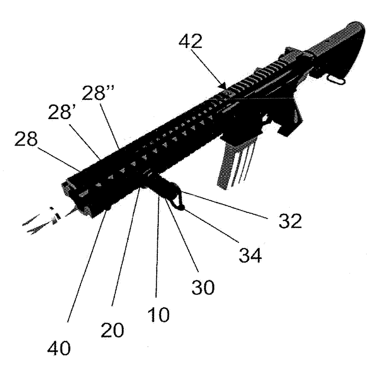
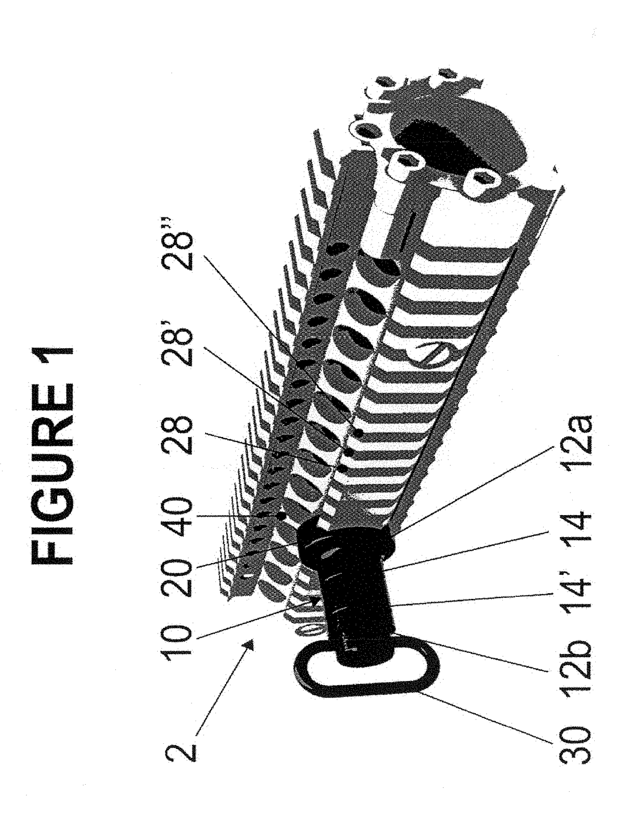
[0067]Turning first to FIG. 1, a finger stop with a swivel attachment 2 (“finger stop”) sometimes referred to as a “thenar” stop, attached to a rail 40 is shown. The finger stop 2 is comprised, generally, of a cylinder 10, an adapter 20 and a detachable sling swivel portion 30.

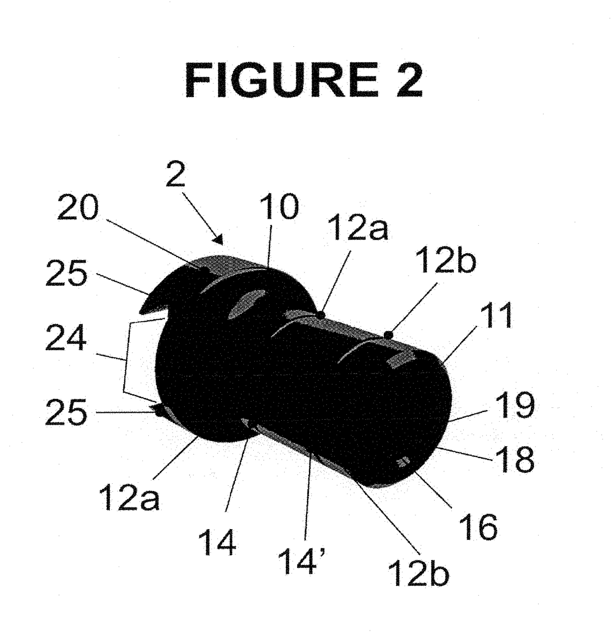
[0068]Turning to FIG. 2, a closer look at the cylinder portion 10 is provided. The cylinder 10 is generally round and hollow, having an aperture, or pair of connected apertures of differing diameters, centered axially that pierces both the proximal end 12a and distal end 12b of the cylinder 10, relative to the rail 40.

[0069]...


PUM


Abstract

A finger stop with a swivel attachment for attachment to the rail of a weapon. The finger stop is comprised, generally, of a cylinder, apparatus for attaching to a weapon rail, and a detachable sling swivel portion. Apparatus for securing the finger stop to a rail system include several types for securing to a number of different rail systems such as, e.g., Picatinny, KeyMod, and MLoc. The sling swivel mechanism is comprised generally of a swivel-able, or rotate-able, handle or extension, a protruding connecting portion for securing the sling swivel within the cylinder, and a securing portion that secures the handle in a rotate-able fashion, thereby securing the sling swivel mechanism to the finger stop. This finger stop design allows a user to minimize rail space and clutter on the weapon. This design, by reducing clutter and protuberances on the rail, helps a user increase the smoothness and flow of unslinging and general handling of the weapon.

Description

TECHNICAL FIELD OF THE INVENTION[0001]The present invention relates to the general art of firearms and more specifically to finger stops technology for integrating sling swivels onto firearms.BACKGROUND OF THE INVENTION[0002]When a rifle is to be used, the type of sling swivel on the rifle can be critical. When a rifle is carried, it is typically carried with a sling, on one's back, or at the alert position for comfort and efficiency. The sling typically extends from the butt end of the stock to somewhere along a rail system that surrounds the barrel. Often, the front end of the sling is attached to the rail by some piece of apparatus. In a number of typical cases, the apparatus is comprised of two or more parts, a part that attaches to the rail of the rifle, usually along the barrel portion, and another, separate part that attaches to the sling. Often, portions of these parts protrude.[0003]Such arrangements can easily result in a multitude of parts attached or hanging from the rai...

Claims


Application Information

Patent Timeline
Patent Type & Authority Applications(United States)
IPC IPC(8): F41C23/02F41C27/22
CPCF41C27/22F41C23/02
Inventor KOLB, JOHN CLIFFORDGISH, MATTHEW DAVIDJONES, JEREMY MCCONNELL
Owner KOLB JOHN CLIFFORD
Learn More