Laundry treating appliance with a static tub and a water trap vapor seal
a technology of static tub and laundry machine, which is applied in the direction of washing machine with receptacles, textiles and papermaking, other washing machines, etc., can solve the problems of reducing the service life of the laundry machin
- Summary
- Abstract
- Description
- Claims
- Application Information
AI Technical Summary
Benefits of technology
Problems solved by technology
Method used
Image
Examples
first embodiment
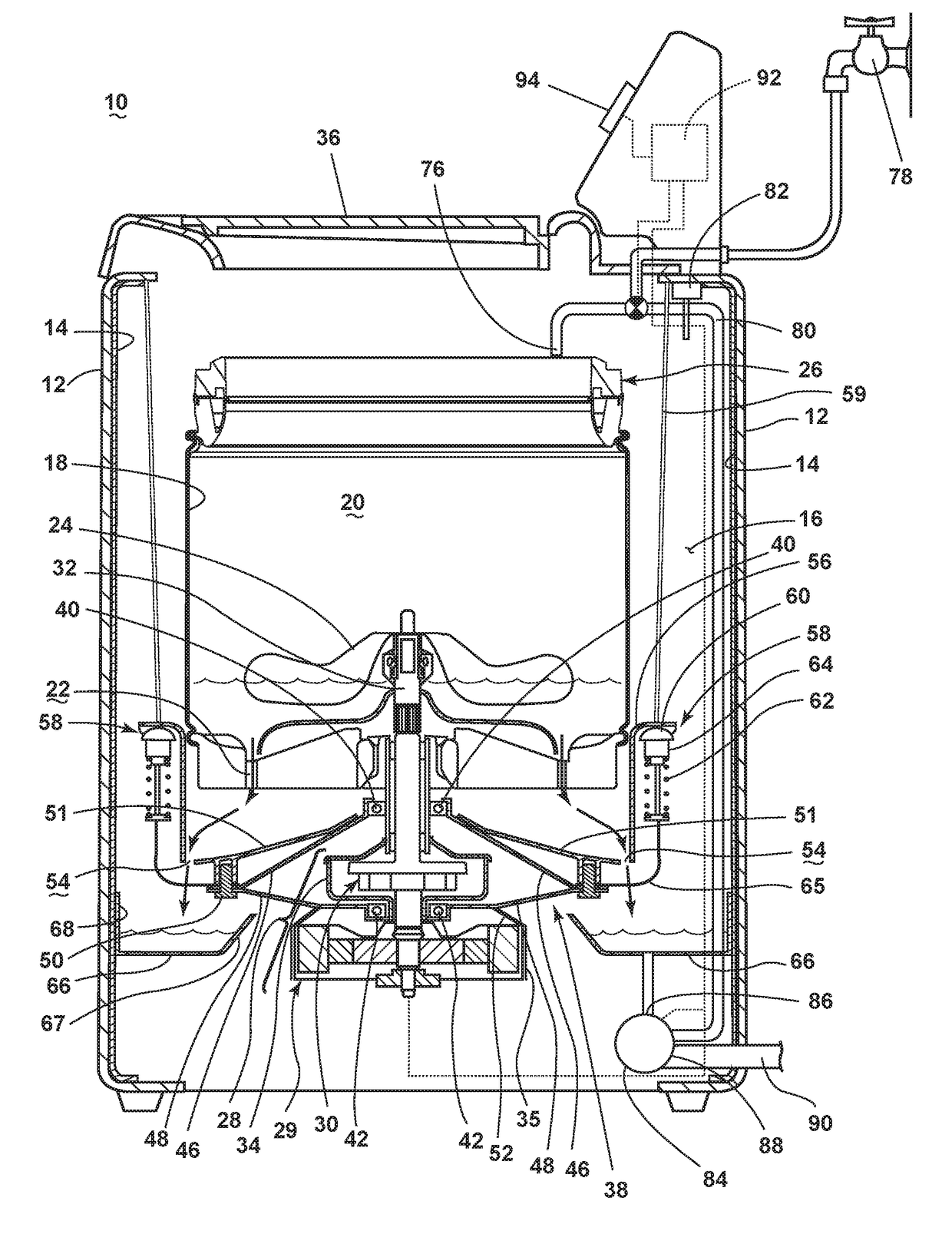
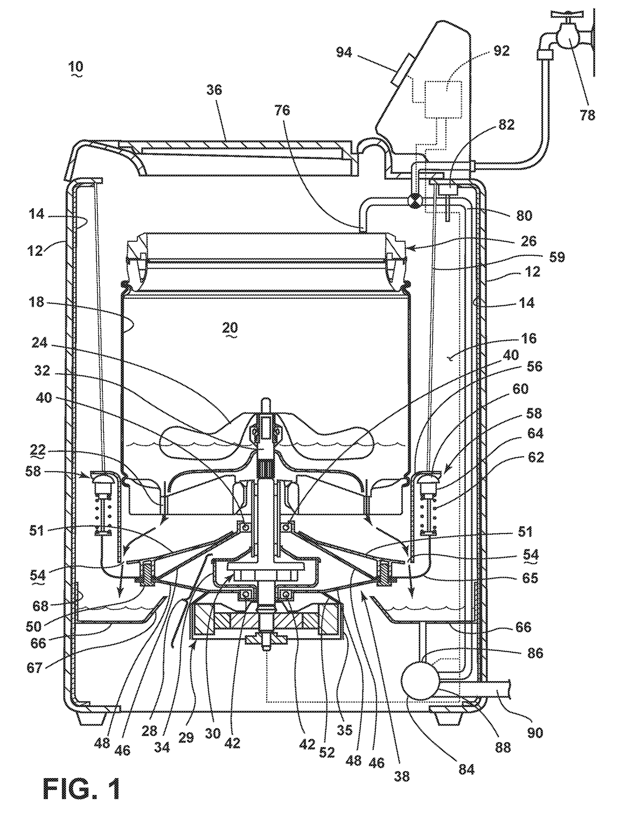
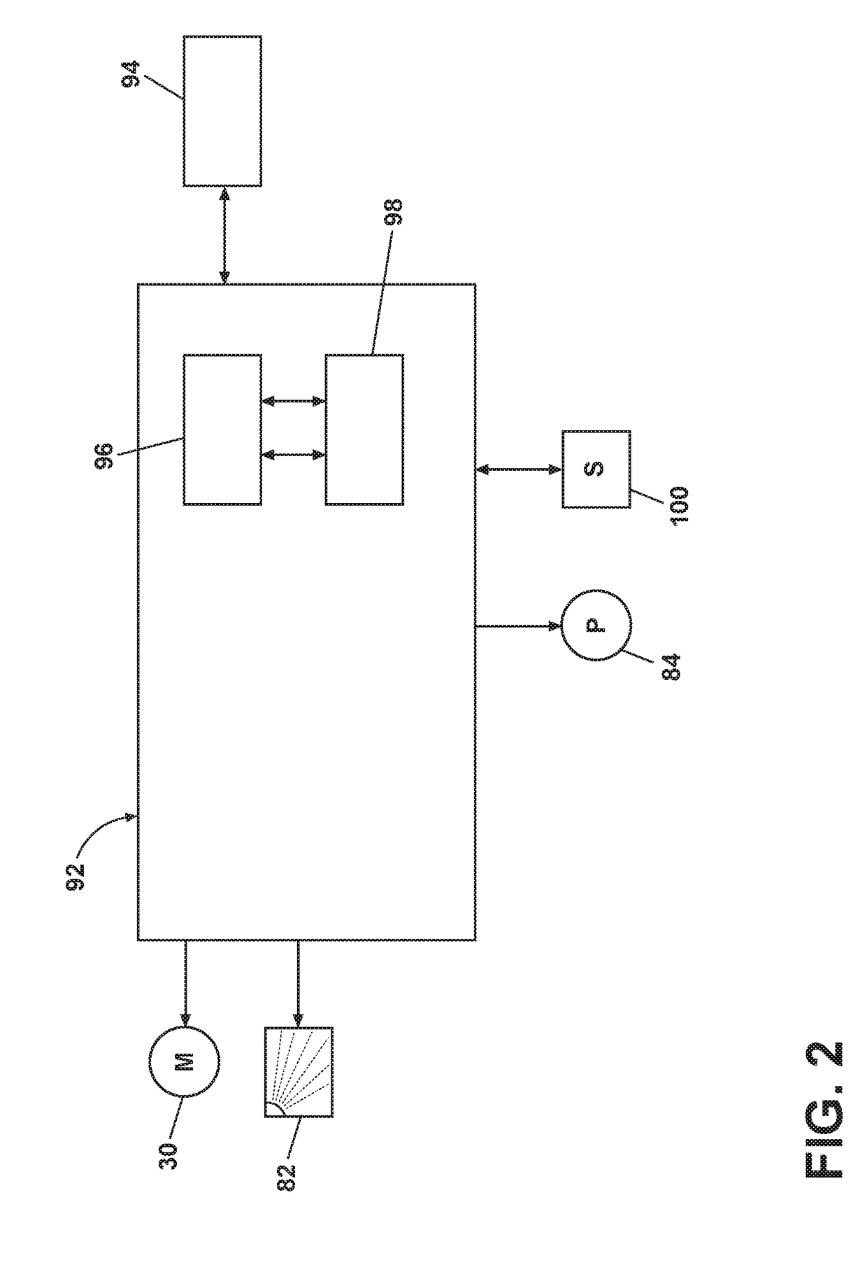
[0013]Referring now to the drawings, FIG. 1 is a schematic view of an exemplary laundry treating appliance 10 in the form of a washing machine according to the invention. While the laundry treating appliance 10 is illustrated as a vertical axis, top-fill washing machine, the invention may have applicability in other laundry treating appliances, such as a horizontal axis washing machine, a combination laundry treating appliance and dryer, an extractor, a non-aqueous laundry treating appliance, and a tumbling or stationary refreshing / revitalizing machine, for example.
[0014]The washing machine 10 may include a cabinet or housing 12, and a static wash tub 14 which is in fixed position with respect to the cabinet 12. In one example, as illustrated in FIG. 1, the static wash tub 14 may be integrated to the cabinet 12, and define an interior 16 of the washing machine 10. By “static wash tub,” it is not necessarily meant that the tub is fixedly integrated to the cabinet 12. Alternately, the...
second embodiment
[0049]Referring to FIG. 3, a schematic cross-sectional view of a laundry treating appliance with a static wash tub according to the invention is illustrated wherein the laundry treating appliance is in the wash phase.
[0050]The primary difference between the first embodiment in FIG. 1 and the second embodiment in FIG. 3 may be a flange 102 mounted to the closure 51. As illustrated, the flange 102 may be coupled to a low end portion of the closure 51 such that the flange 102 may extend downwardly from the low end portion of the closure 51 until one end portion of the flange 102 contacts the bottom of the catch basin 66 during the wash phase.
[0051]The flange 102 may be configured to form a seal when the flange 102 contacts the bottom of the catch basin 66. As a result, the flange 102 may act as a trap for confining the wash liquid and / or vapor inside the interior 16 of the static wash tub 14. For example, the flange 102 may form a trap seal with the bottom of the catch basin 66 for blo...
third embodiment
[0052]FIG. 4 is a schematic cross-sectional view of the laundry treating appliance of FIG. 3 according to the invention, where the laundry treating appliance in FIG. 4 is in a spin extraction phase. When the wash phase is complete, the wash liquid may be drained out of the catch basin 66, followed by the spin extraction phase where the wash basket 18 rotates at a high spin speed.
[0053]It is understood that, during the high speed spin extraction phase, the wash basket 18 may be subject to a translational and / or vertical movement from any unbalance of non-uniformly distributed laundry items in the wash basket 18. The translational and / or vertical movement of the wash basket 18 may be transmitted to other coupled components in the form of vibration. In one example, vibration may transmit to the bearing housing 38, the flange 102, the flexure element 65, and the suspension system 58.
[0054]The suspension system 58 may move horizontally and / or vertically for damping out the vibrations of ...
PUM
 Abstract
Description
Claims
Application Information
 - R&D
- Intellectual Property
- Life Sciences
- Materials
- Tech Scout
- Unparalleled Data Quality
- Higher Quality Content
- 60% Fewer Hallucinations
Browse by: Latest US Patents, China's latest patents, Technical Efficacy Thesaurus, Application Domain, Technology Topic, Popular Technical Reports.
© 2025 PatSnap. All rights reserved.Legal|Privacy policy|Modern Slavery Act Transparency Statement|Sitemap|About US| Contact US: help@patsnap.com


