
Method and apparatus for undercowl flow diversion cooling

a technology of flow diversion and cooling apparatus, which is applied in the direction of machines/engines, efficient propulsion technologies, stators, etc., can solve the problems of temperature rise of some electronics, electrical and electronic components may be exposed to even higher temperatures, and temperature can have undesirable effects on electrical and electronic components

Active Publication Date: 2018-05-17
GENERAL ELECTRIC CO
View PDF4 Cites 22 Cited by
  • Summary
  • Abstract
  • Description
  • Claims
  • Application Information

AI Technical Summary

Benefits of technology

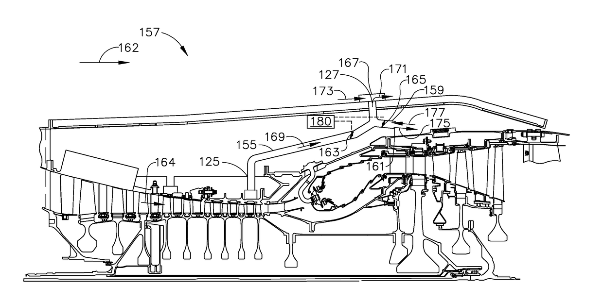
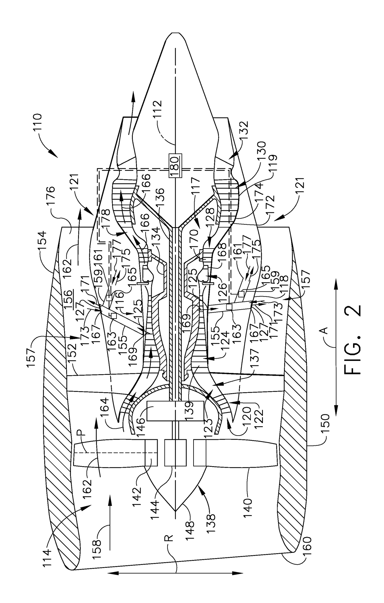
The patent discusses cooling systems for gas turbine engines. The cooling system includes a first conduit that channels fluid from the inner casing to the outer casing during one mode of operation. The cooling system also includes a second conduit that channels fluid from the outer casing to the cavity during another mode of operation. The cooling system further includes at least one valve that can switch between the first and second conduits to channel fluid in different directions. This allows for efficient cooling of the engine during different operating modes.

Problems solved by technology

In addition to experiencing elevated temperatures during operation, the electronics may be exposed to even higher temperatures during the period after engine shut down.
As a result, the temperature of some of the electronics may actually rise as the hottest engine portions cool down.
Such temperatures can have undesirable effects on electrical and electronic components.
While an abrupt catastrophic failure of an electronic component may not always occur, progressive breakdown due to elevated temperature and thermal cycling can reduce the usable lifetime of such electronic components.
Where such components are placed at remote locations in the engine, increases in the length of connecting cables also increases engine weight and tends to increase SFC while also complicating maintenance activities.
Furthermore, in such known gas turbine engines, such problems are compounded during soakback when there is no cooling flow.
An extended delay after operation of such known gas turbine engines before servicing them may be required.

Method used


Image

  • Method and apparatus for undercowl flow diversion cooling
  • Method and apparatus for undercowl flow diversion cooling
  • Method and apparatus for undercowl flow diversion cooling

Examples


Embodiment Construction

[0016]In the following specification and the claims, reference will be made to a number of terms, which shall be defined to have the following meanings.

[0017]The singular forms “a”, “an”, and “the” include plural references unless the context clearly dictates otherwise.

[0018]“Optional” or “optionally” means that the subsequently described event or circumstance may or may not occur, and that the description includes instances where the event occurs and instances where it does not.

[0019]Approximating language, as used herein throughout the specification and claims, may be applied to modify any quantitative representation that could permissibly vary without resulting in a change in the basic function to which it is related. Accordingly, a value modified by a term or terms, such as “about”, “approximately”, and “substantially”, are not to be limited to the precise value specified. In at least some instances, the approximating language may correspond to the precision of an instrument for...


PUM


Abstract

A cooling system includes a first conduit positioned within a cavity and extends from a radially inner casing aperture to a radially outer casing aperture. The cooling system also includes a second conduit coupled in flow communication with the first conduit and extending into the cavity. The cooling system further includes at least one valve positioned within the first conduit and the second conduit. The at least one valve and the first conduit are configured to channel a first fluid from the radially inner casing aperture to the radially outer casing aperture during a first mode of operation. The at least one valve, the second conduit, and the first conduit are configured to channel a second fluid from the radially outer casing aperture to the cavity during a second mode of operation.

Description

BACKGROUND[0001]The field of the disclosure relates generally to gas turbine engines and, more particularly, to a method and apparatus for cooling an undercowl space in gas turbine engines.[0002]Gas turbine engines typically include an undercowl space or engine core compartment as a part of the engine architecture. As gas turbine engine efficiency is improved, pressure ratios of fans and compressors, internal engine temperatures are expected to rise substantially, resulting in higher temperature for the engine core compartment and components. Engine core compartment components include electronics and other line replaceable units (LRUs). Such electronic components in known gas turbine engines, including full authority digital engine (or electronics) controls (FADECs), may be particularly sensitive to increasing engine core compartment temperatures both during gas turbine engine operation and during thermal soakback after engine shutdown. Although the electronics are not located in th...

Claims


Application Information

Patent Timeline
IPC IPC(8): B64D33/08F02C7/18F02C9/18
CPCB64D33/08F02C7/18F02C9/18F05D2260/20F01D9/065F01D25/12F02C7/12B64D27/16F02K3/075F05D2260/608Y02T50/40Y02T50/60F02C7/16
Inventor ELBIBARY, MOHAMEDWIBERG, CLARK GEORGECLARKE, BRANDON CHRISTOPHERNOLTE, STEVEN EDWARD
Owner GENERAL ELECTRIC CO
Learn More