Keyswitch

a key and keypad technology, applied in the field of keyswitch, can solve the problems of fatigue of the fingers of the user inconvenient user pressing the keycap successively, etc., and achieve the effect of easy pressing down the keycap quickly, large return force, and relatively small force feedback

Active Publication Date: 2018-05-17
DARFON ELECTRONICS (SUZHOU) CO LTD +1
View PDF6 Cites 2 Cited by
  • Summary
  • Abstract
  • Description
  • Claims
  • Application Information

AI Technical Summary

Benefits of technology

[0004]An objective of the invention is to provide a keyswitch. The keyswitch uses a combination of springs connected in series to provide a force feedback which is light first and then heavy, so that a user can easily press the keycap of the keyswitch quickly and the keycap can return quickly after the pressing is released.
[0007]Therefore, for the above keyswitches, before the keycap reaches the transition position, each of the first spring and the second spring contributes to the elastic deformation, so the spring constant of the combination of springs is relatively small. The user can easily press down the keycap quickly. The force feedback is also relatively small. After the keycap moves downward beyond the transition position, one of the first and second springs is compressed to the corresponding solid height so that said spring cannot provide further elastic deformation. Only the other one of the first and second springs can continue contributing to the elastic deformation. Therefore, the spring constant of the combination of springs increases and the keycap can obtain a relatively large return force, so that when the user no longer presses the keycap, the keycap can return to its original position quickly. Thereby, the keycap can move up and down quickly. The user can sense a light first and then heavy pressing feeling, which reduces the degree of fatigue of the user when the user manipulates the keyswitch.

Problems solved by technology

However, because the return force is small, the time for the pressed keycap to return its original position is long, which is inconvenient for the user to press the keycap successively in a short time.
However, because the return force is large, the resistant force to a user pressing the keycap is large, so that the user needs to press the keycap by a larger force, which brings a fatigue to the fingers of the user so that it is inconvenient for the user to press the keycap successively in a short time.
Furthermore, the deformation mechanism of the rubber dome is different from the linear deformation of the spring.
Therefore, in use, the user can sense a large threshold of pressing force, but the pressing force by the user after the threshold is small; furthermore, the whole elastic energy stored by the deformed rubber dome is not high.
On the whole, compared with the keyswitch using the spring with a high spring constant, the keycap of the keyswitch using the rubber dome still takes a relative long time to return to its original position.
Therefore, the current keyswitches (no matter using a spring or a rubber dome) cannot provide their keycaps an action of being pressed down quickly and returning quickly which can reduce the degree of fatigue of the fingers of the user when the user manipulates the keyswitch in some environments such as of electronic sports.

Method used


Image

  • Keyswitch
  • Keyswitch
  • Keyswitch

Examples


Embodiment Construction

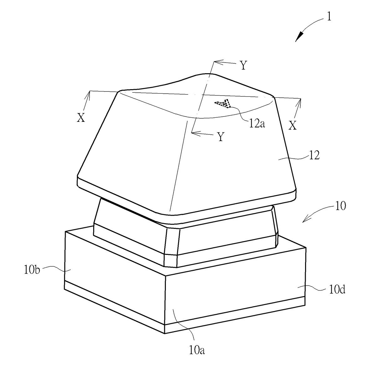
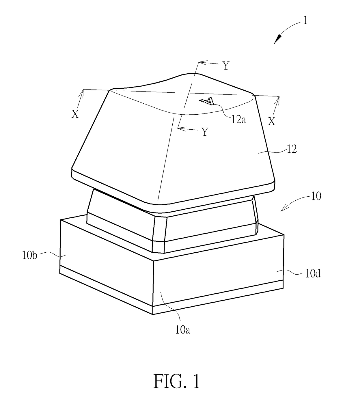
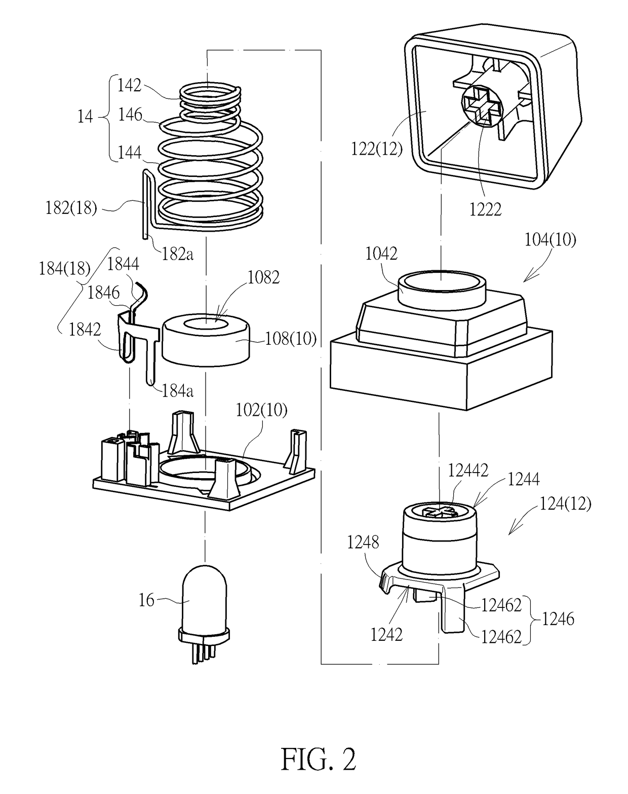
[0034]Please refer to FIG. 1 to FIG. 5. A keyswitch 1 of an embodiment according to the invention includes a base 10, a keycap 12, a return force mechanism 14, a light source 16, and a switch 18. The keycap 12 is disposed above the base 10. The return force mechanism 14 is disposed between the base 10 and the keycap 12. By a sliding engagement of the base 10 with the keycap 12, the keycap 12 can move parallel to a direction D1 (indicated by an arrow in FIG. 4 and FIG. 5) selectively toward or away from the base 10. Therein, in the view point of FIG. 4 or FIG. 5, the direction D1 is substantially a vertical direction. In the embodiment, the return force mechanism 14 is a combination of springs which includes a first spring 142 and a second spring 144. The first spring 142 and the second spring 144 are connected in series and are disposed between the base 10 and the keycap 12. An upper end the first spring 142 is against the keycap 12. A lower end of the first spring 142 is connected ...


PUM


Abstract

A keyswitch uses a combination of springs connected in serial for providing a return force to a keycap of the keyswitch. When the keycap moves toward a base of the keyswitch beyond a transition position, one of the springs stops continuously deforming. It leads to an increment of the elastic coefficient of the combination of springs and an increment of the elastic stored energy by the combination of springs. Therefore, during a pressing on the keycap, the keycap can provide a light force feedback and then a heavy force feedback to a user. Further, the keyswitch can use a switch with a lateral motion, which can reduce influence of a resilient force produced by the switch on the up and down movement of the keycap. The keyswitch also can use an elastic piece disposed beside the keycap, which can provide a tactile feedback to the user.

Description

CROSS REFERENCE TO RELATED APPLICATIONS[0001]This application is a continuation application of and claims the priority benefit of U.S. patent application Ser. No. 15 / 422,443, filed on Feb. 1, 2017, now pending. The entirety of the above-mentioned patent application is hereby incorporated by reference herein and made a part of this specification.BACKGROUND OF THE INVENTION1. Field of the Invention[0002]The invention relates to a keyswitch, and especially relates to a keyswitch using a spring for producing return force.2. Description of the Prior Art[0003]Keyswitches on the market commonly use a spring or a rubber dome for producing a required return for the keycap thereof. In general, the used spring has a single fixed spring constant. If the spring constant is small, the return force produced by the spring is small and a resistant force to a user pressing the keycap is also small, so that the user can press down the keycap quickly. However, because the return force is small, the tim...

Claims


Application Information

Patent Timeline
Patent Type & Authority Applications(United States)
IPC IPC(8): H01H13/14H01H13/52H01H13/02H01H13/10H01H13/28
CPCH01H2215/00H01H2201/018H01H13/52H01H13/023H01H13/14H01H13/10H01H13/28H01H1/24H01H3/42H01H2205/004H01H2215/028H01H2215/03
Inventor LIAO, RUI-MINGYEN, CHIH-CHUNGLO, HUNG-CHIEHLIU, CHIA-HUNG
Owner DARFON ELECTRONICS (SUZHOU) CO LTD
Why Eureka
Try Eureka