Rotor unit, rotating electrical machine, and method for manufacturing rotor unit

a technology of rotating electrical machines and rotors, which is applied in the direction of manufacturing stator/rotor bodies, magnetic circuit rotating parts, and shape/form/construction of magnetic circuits, etc. it can solve the problems of rotor core and magnet holder separation, and the axial fixing strength of the rotor core cannot be disclosed, so as to improve the fixing strength of the rotor core. , the manufacturing process of the rotor

Active Publication Date: 2013-10-03
NIDEC CORP
View PDF7 Cites 24 Cited by
  • Summary
  • Abstract
  • Description
  • Claims
  • Application Information

AI Technical Summary

Benefits of technology

[0012]According to the first exemplary invention of the present application, in the outer peripheral surface of the rotor core, a portion of resin that constitutes the holder is present between the plurality of steel sheets that constitutes the rotor core. This improves the fixing strength of the rotor core and the holder.
[0013]According to the second exemplary invention of the present application, the manufacturing process of the rotor core and the holder is shortened by the insert molding. Additionally, a portion of resin that constitutes the holder is present between the plurality of steel sheets that constitutes the rotor core. This improves the fixing strength of the rotor core and the holder. Additionally, since the separation between the rotor core and the holder is suppressed, the magnets can be easily press-fitted.

Problems solved by technology

However, WO-A 2006-008964 does not disclose how to obtain the axial fixing strength between the rotor core and the magnet holder.
Particularly, if the rotor core and the magnet holder are not firmly fixed in an axial direction when the magnets are press-fitted to the magnet holder in the axial direction, there is a concern that the rotor core and the magnet holder may be separated from each other due to the load at the time of press-fitting.

Method used


Image

  • Rotor unit, rotating electrical machine, and method for manufacturing rotor unit
  • Rotor unit, rotating electrical machine, and method for manufacturing rotor unit
  • Rotor unit, rotating electrical machine, and method for manufacturing rotor unit

Examples


Embodiment Construction

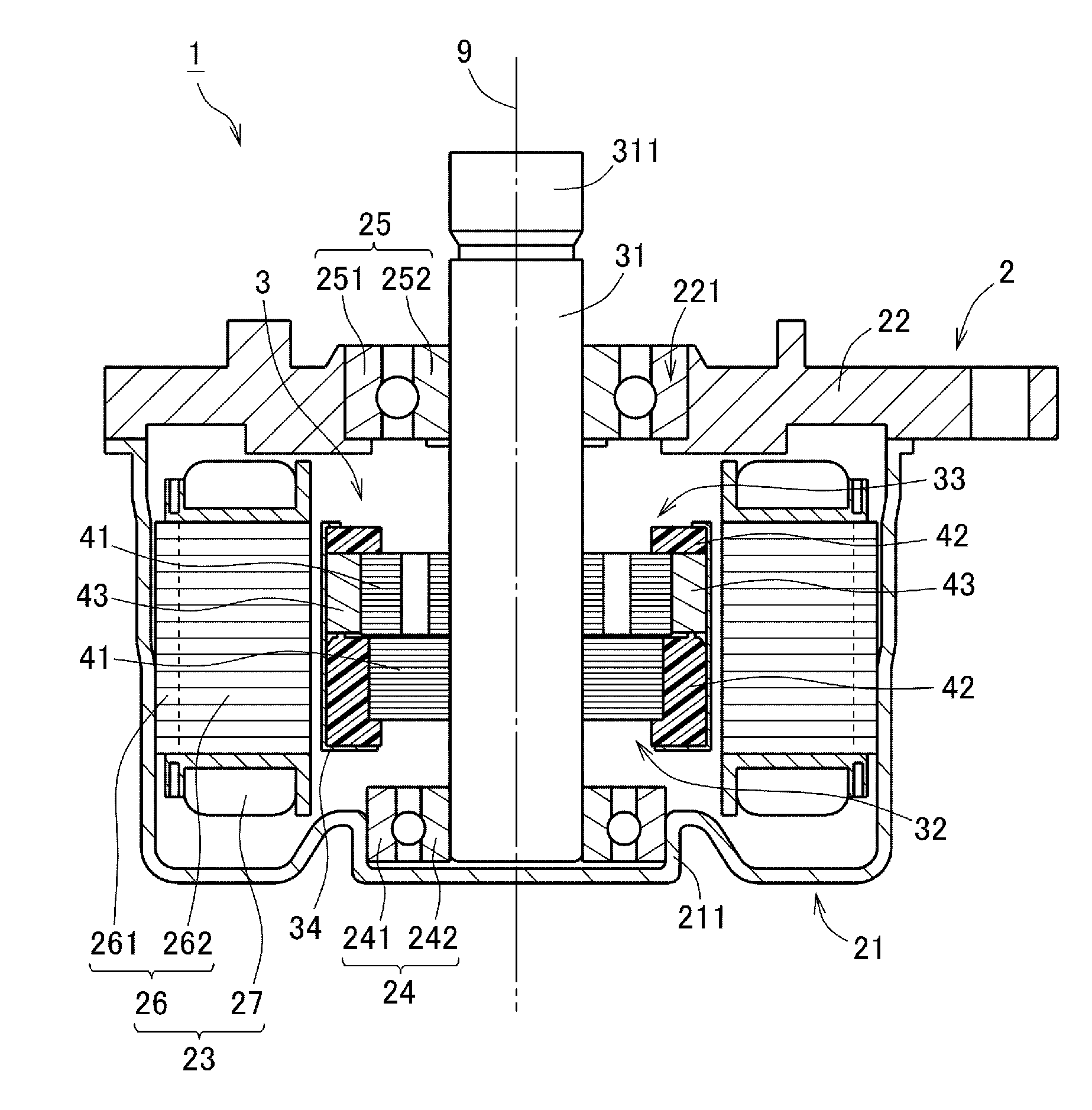
[0027]Exemplary embodiments of the invention will be described below, referring to the drawings. In addition, the shapes and positional relationship of respective portions will be described with a direction along the central axis of a rotating electrical machine being a vertical direction. However, this merely defines the vertical direction for the convenience of description, and does not limit the posture of a rotor unit and a rotating electrical machine related to the invention when being used.

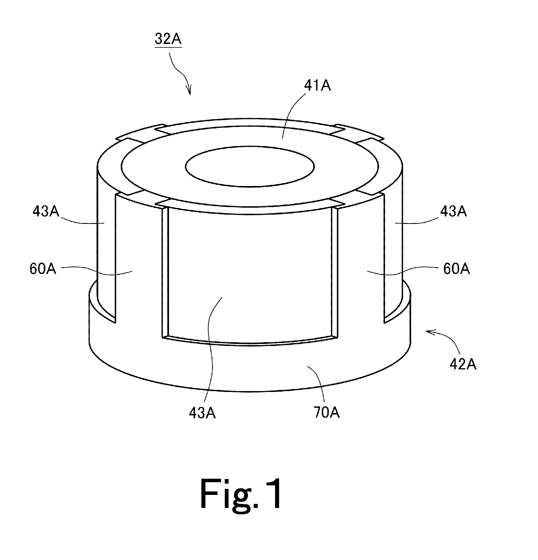
[0028]FIG. 1 is a perspective view of a rotor unit 32A for a rotating electrical machine related to one embodiment of the invention. As shown in FIG. 1, the rotor unit 32A includes a rotor core 41A, a holder 42A, and a plurality of magnets 43A.

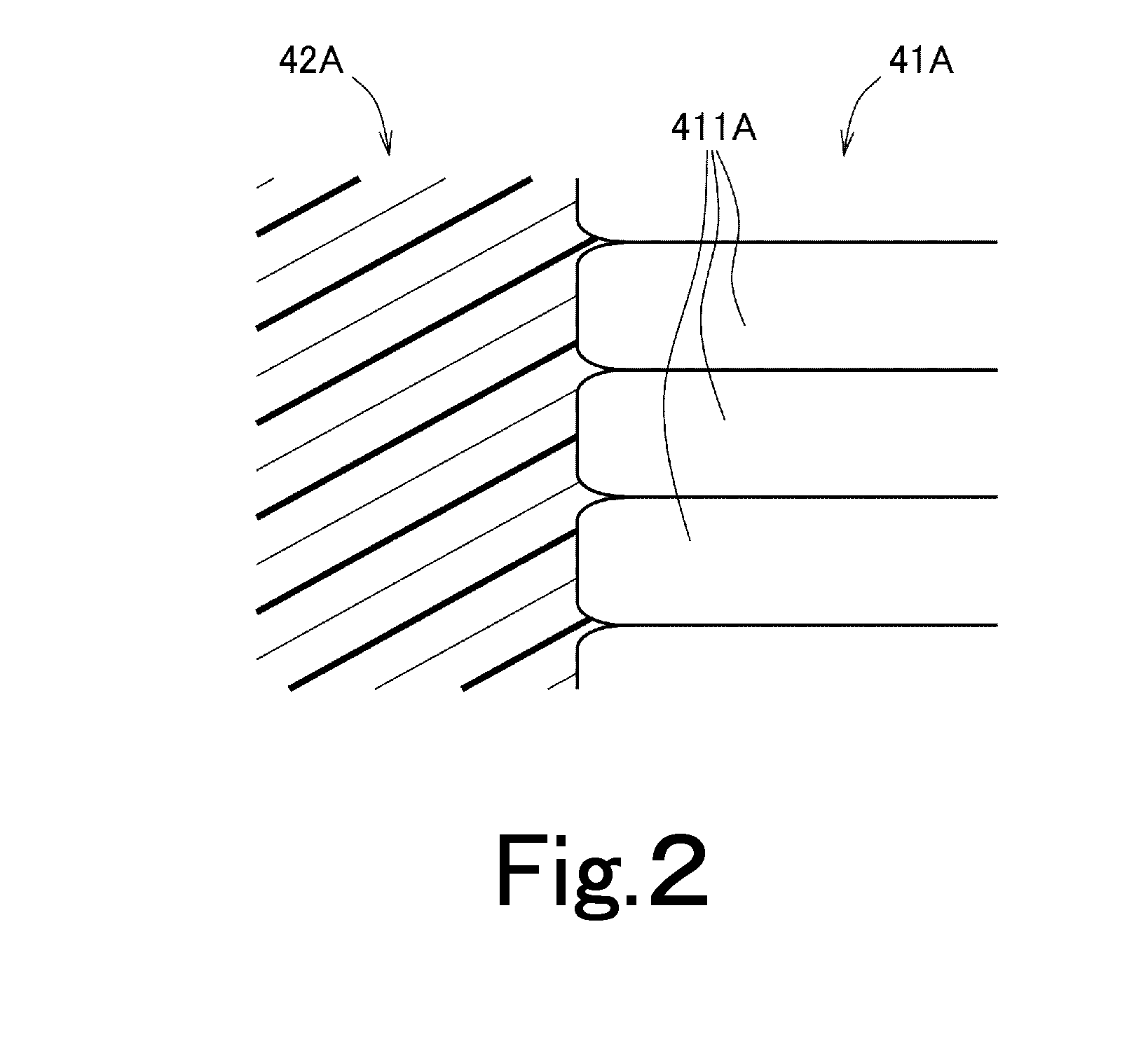
[0029]The rotor core 41A is an annular member made of laminated steel sheets that are vertically laminated. The holder 42A is a member made of resin, which holds the magnets 43A. The holder 42A has a plurality of partitioning portions 60A and a couplin...


PUM

PropertyMeasurementUnit
widthaaaaaaaaaa
shapeaaaaaaaaaa
axial fixing strengthaaaaaaaaaa

Abstract

A rotor unit includes a rotor core made of laminated steel sheets that are vertically laminated, and a holder made of resin. The rotor core and the holder are fixed together through insert molding. For this reason, the process of manufacturing the rotor core and the holder is shortened. Additionally, in the outer peripheral surface of the rotor core, a portion of resin that defines the holder is present between the plurality of steel sheets that defines the rotor core. For this reason, the fixing strength of the rotor core and the holder improves. Additionally, since a separation between the rotor core and the holder is prevented, magnets can be easily press-fitted.

Description

BACKGROUND OF THE INVENTION[0001]1. Field of the Invention[0002]The present invention relates to a rotor unit, a rotating electrical machine, and a method for manufacturing a rotor unit.[0003]2. Description of the Related Art[0004]In the related art, an inner rotor type motor that rotates a rotor unit having magnets inside a coil is known. For example, WO-A 2006-008964 discloses a brushless motor including a stator, and a rotor arranged inside the stator.[0005]The rotor of WO-A 2006-008964 includes a rotor shaft, a rotor core, a magnet holder, and six rotor magnets. Paragraph 0026 of WO-A 2006-008964 discloses that the rotor core is fixed to the rotor shaft, and the six rotor magnets are attached to an outer periphery of the rotor core. Additionally, Paragraph 0027 of WO-A 2006-008964 discloses that the magnet holder is fixed to the rotor shaft.RELATED ART DOCUMENT[0006][Patent Document 1] WO-A 2006-008964[0007]Additionally, Paragraph 0029 of WO-A 2006-008964 descloses that a fittin...

Claims


Application Information

Patent Timeline
Patent Type & Authority Applications(United States)
IPC IPC(8): H02K1/28H02K15/02H02K1/27
CPCH02K1/278H02K15/03Y10T29/49012H02K1/28H02K15/02H02K1/27H02K21/14H02K15/12B62D5/04
Inventor HAGA, HIDEHIROKAWAMOTO, TATSUROMURAKAMI, SHUNSUKE
Owner NIDEC CORP
Why Eureka
Try Eureka