Rotor

a technology of rotating parts and rotors, which is applied in the direction of manufacturing stator/rotor bodies, magnetic circuit rotating parts, and magnetic circuit shape/form/construction, etc., can solve the problems of difficult to firmly fix the plurality of thin plate cores, and the region of caulking in the rotor core is more difficult to secure, so as to prevent the leakage of magnetic flux from the outer core portion to the inner core portion, the effect of reducing the risk of slipping

Active Publication Date: 2014-12-30
NIDEC CORP
View PDF16 Cites 23 Cited by
  • Summary
  • Abstract
  • Description
  • Claims
  • Application Information

AI Technical Summary

Benefits of technology

[0014]According to the second preferred embodiment of the present invention, the plurality of outer core portions and the plurality of magnets are alternately arranged in the circumferential direction, and the magnetic pole surfaces of the magnet are directed in the circumferential direction. Therefore, unlike any general SPM type and IPM type rotors, the magnetic flux of the plurality of magnets can be effectively used. In addition, since the inner core portion and the outer core portions are connected by the resin portion, leakage of the magnetic flux from the outer core portions to the inner core portion is significantly reduced and prevented. In addition, the rotor according to a preferred embodiment of the present invention includes the caulking portions preferably provided in both the outer core portions and the inner core portion. Accordingly, the plurality of thin plate cores are firmly fixed. Moreover, in a preferred embodiment of the present invention, the inner core caulking portions are disposed in regions widened by the protruding portions. Accordingly, the inner core caulking portions can be made larger in size. As a result, the fixing strength of the plurality of thin plate cores may further be enhanced by the inner core caulking portions.

Problems solved by technology

However, when the cylindrical core is provided, it is difficult to firmly fix the plurality of thin plate cores only by performing caulking of the plurality of cores on the outside.
When the inner rotor type motor is to be reduced in size, it is more difficult to secure a region for performing caulking in the rotor core.

Method used


Image

  • Rotor
  • Rotor
  • Rotor

Examples


first preferred embodiment

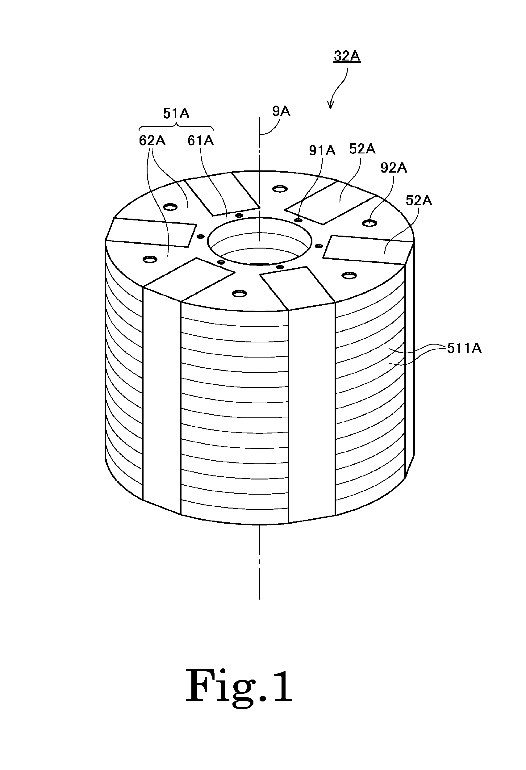
[0027]FIG. 1 is a perspective view of a rotor 32A according to a first preferred embodiment of the present invention. The rotor 32A is preferably used in an inner rotor type motor, for example. As illustrated in FIG. 1, the rotor 32A preferably includes a laminated core 51A and a plurality of magnets 52A. The laminated core 51A is defined by a plurality of thin plate cores 511A laminated in the axial direction. The plurality of magnets 52A are arranged in the circumferential direction around a center axis 9A extending vertically.

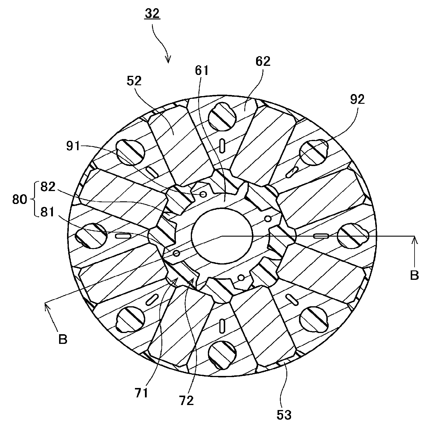
[0028]The laminated core 51A includes an inner core portion 61A and a plurality of outer core portions 62A. The inner core portion 61A axially extends in a cylindrical shape in a region located farther radially inward than the magnets 52A. The plurality of outer core portions 62A are arranged in the circumferential direction in a region located farther radially outward than the inner core portion 61A. The plurality of outer core portions 62A and the pluralit...

second preferred embodiment

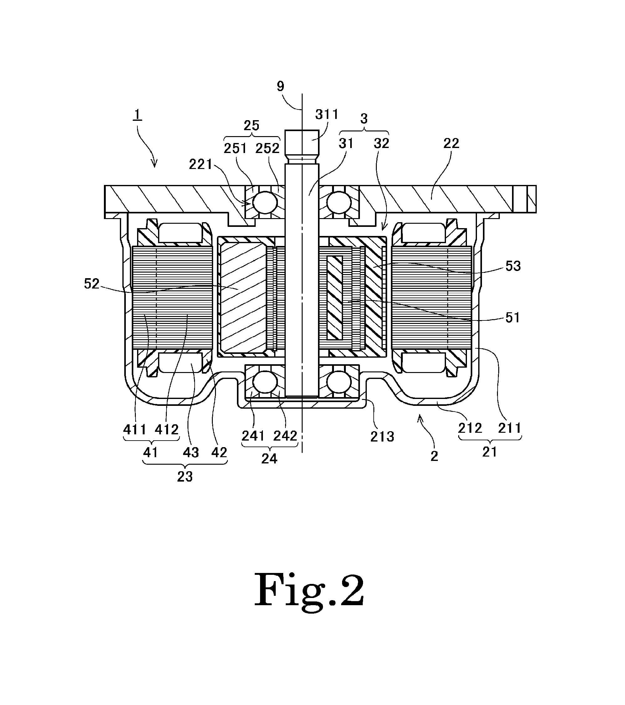
[0031]Subsequently, a second preferred embodiment of the present invention will be described. FIG. 2 is a longitudinal sectional view of a motor 1 according to the second preferred embodiment. The motor 1 in this preferred embodiment is preferably mounted in, for example, a vehicle and is used, for example, as a driving source of an engine cooling fan, an oil pump, etc. However, the motor of various preferred embodiments of the present invention may also be used for purposes other than the engine cooling fan or the oil pump. For example, the motor of various preferred embodiments of the present invention may also be used as a driving source for power steering. In addition, the motor of various preferred embodiments of the present invention may be mounted in electric appliances, office automation equipment, medical equipment, and the like to generate various driving forces, for example.

[0032]The motor 1 is a so-called inner rotor type motor in which a rotor 32 is disposed in the radi...


PUM


Abstract

A laminated core of a rotor includes an inner core portion and a plurality of outer core portions. The inner core portion axially extends in a cylindrical shape in a region located more radially inward than magnets. The outer core portions are arranged in a circumferential direction in a region located more radially outward than the inner core portion. The plurality of outer core portions and a plurality of the magnets are alternately arranged in the circumferential direction. Accordingly, magnetic flux generated from a pair of magnetic pole surfaces of the plurality of magnets can be effectively used. In addition, the laminated core includes caulking portions in each of the inner core portion and the plurality of outer core portions. Accordingly, a plurality of thin plate cores are firmly fixed.

Description

BACKGROUND OF THE INVENTION[0001]1. Field of the Invention[0002]The present invention relates to a rotor and a motor.[0003]2. Description of the Related Art[0004]A so-called inner rotor type motor in which a rotor is disposed inside an armature is known. The types of rotors used in the inner rotor type motor are mainly classified into an SPM (Surface Permanent Magnet) type rotor in which a plurality of magnets are attached to the outer circumferential surface of a rotor core and an IPM (Interior Permanent Magnet) type rotor in which magnets are buried in a rotor core.[0005]When the SPM type rotor is used, the armature and the magnets can be placed in proximity to each other. Therefore, the magnetic force of the magnets can be effectively used. However, in the SPM type rotor, measures to prevent the magnets from escaping outward due to a centrifugal force during high-speed rotation need to be prepared. On the other hand, when the IPM type rotor is used, there is no concern of the mag...

Claims


Application Information

Patent Timeline
Patent Type & Authority Patents(United States)
IPC IPC(8): H02K15/03H02K1/30H02K21/12H02K1/27
CPCH02K1/2773H02K15/03H02K1/30H02K1/2706
Inventor ASAHI, KYOHEIHAMAGISHI, KENICHIROTANAKA, KUNIAKITERADA, SUSUMU
Owner NIDEC CORP
Why Eureka
Try Eureka