Liquid discharge recording head, liquid discharge recording apparatus, and method for manufacturing liquid discharge head

a recording head and liquid discharge technology, applied in the direction of mountings, instruments, printing, etc., can solve the problems of blade b>321/b> damage, uneven wiping, and damage beyond recovery of recording head, so as to improve the fixing strength and perform more reliably , the effect of wide capping area

Inactive Publication Date: 2005-12-13
CANON KK
View PDF17 Cites 22 Cited by
  • Summary
  • Abstract
  • Description
  • Claims
  • Application Information

AI Technical Summary

Benefits of technology

[0029]In accordance with the present invention, the orifice plate is fixed not only to the front face of recording head, but also, to the two face adjacent thereto. With the increased number of fixing faces of orifice plate to the recording head, the fixing strength is enhanced. Therefore, it becomes possible to prevent the edge portion of orifice plate from being peeled off by use of the wiping blade.
[0030]Further, in accordance with the liquid discharge recording head of the present invention, the orifice plate is structured to be folded along the edge face on the front side of recording head, and provided with the area almost the same as that of front face of recording head. Therefore, it becomes possible to arrange the structure to enable the orifice plate to cover substantially the front face of recording head. Thus, as compared with the structure in which an orifice cover is provided to cover the circumference of an orifice plate, it becomes possible to obtain a wider capping area. As a result, the suction recovery operation can be performed more reliably without using complicated capping mechanism to make it possible to suppress and keep the lower costs of recording apparatus.
[0031]Further, the entire front face of orifice plate is made flat and smooth to make it possible to reduce remaining liquid or wiping unevenness significantly when the wiping operation is carried out by use of the blade. Also, with the flat wiping face, it becomes possible to reduce the damages that may be caused to the blade, and enhance the reliability of the blade as well.
[0032]With these functions, the freedom of designing recording head is increased to be able to promote making the recording head and the recording apparatus itself smaller and reducing the costs of manufacture thereof. Also, it becomes possible to provide the liquid discharge recording head the life of which is implemented to be longer.

Problems solved by technology

If the edge portion of orifice plate should be peeled off even slightly, it advances further by repetition of wiping operations to follow, and the recording head is damaged beyond recovery ultimately.
As a result, remaining liquid on the orifice plate 306 tends to form a pool on the corners of such step when wiping is performed by use of the blade 321 or there is a fear that uneven wiping takes place due to the insufficient contact which is caused by the vibration or jump over of the blade 321.
Furthermore, there is a possibility that the blade 321 is damaged due to the one-sided contact of the blade 321 with the step between the orifice cover 312 and orifice plate 306.
Thus, this structure presents the problem of reliability, too.
In this method, however, it is firstly needed to arrange the structure so that the wiping blade is made detractable from the face of orifice plate, which makes the costs of wiping device higher inevitably.
Secondly, this structure brings about such unfavorable condition as to return dust particles (such as dust, powdered paper, paper fluffs) or excessively viscous ink (ink the volatile component of which has been evaporated), which are collected by the rubbing face of blade by wiping and adhere to it, onto the face of the orifice plate.
In other words, there is a fear that the dust particles or excessively viscous ink collected by the rubbing face of the blade by wiping and adhere to it are transferred and returned to the face of the orifice plate when the wiping blade is retracted or rubbed again to adhere to the face of orifice plate.
As described above, the method that uses the orifice cover or the method for regulating the area where the wiping blade and face of orifice plate are slidably rubbed each other is not very advisable.

Method used


Image

  • Liquid discharge recording head, liquid discharge recording apparatus, and method for manufacturing liquid discharge head
  • Liquid discharge recording head, liquid discharge recording apparatus, and method for manufacturing liquid discharge head
  • Liquid discharge recording head, liquid discharge recording apparatus, and method for manufacturing liquid discharge head

Examples


third embodiment

(Third Embodiment)

[0132]FIG. 8 is a perspective view which shows the liquid discharge recording head in accordance with a third embodiment of the present invention. FIG. 9 is a cross-sectional view which shows the liquid discharge recording head represented in FIG. 8.

[0133]For the liquid discharge recording head of the present embodiment, the folded portions of the orifice plate 101, that is, the extended portions thereof, are bonded to the recording head main body by use of bonding agent. When the orifice plate is bonded to the recording head main body, bonding agent is coated on the contact faces of the folded portions of the orifice plate, and the contact faces on the recording head side. Then, the orifice plate 101 is folded to execute bonding.

[0134]With the structure thus arranged in accordance with the present embodiment, there is no need for use of the pressure plate described earlier. As a result, it is possible to reduce the thickness equivalent to that of two pressure plat...

fourth embodiment

(Fourth Embodiment)

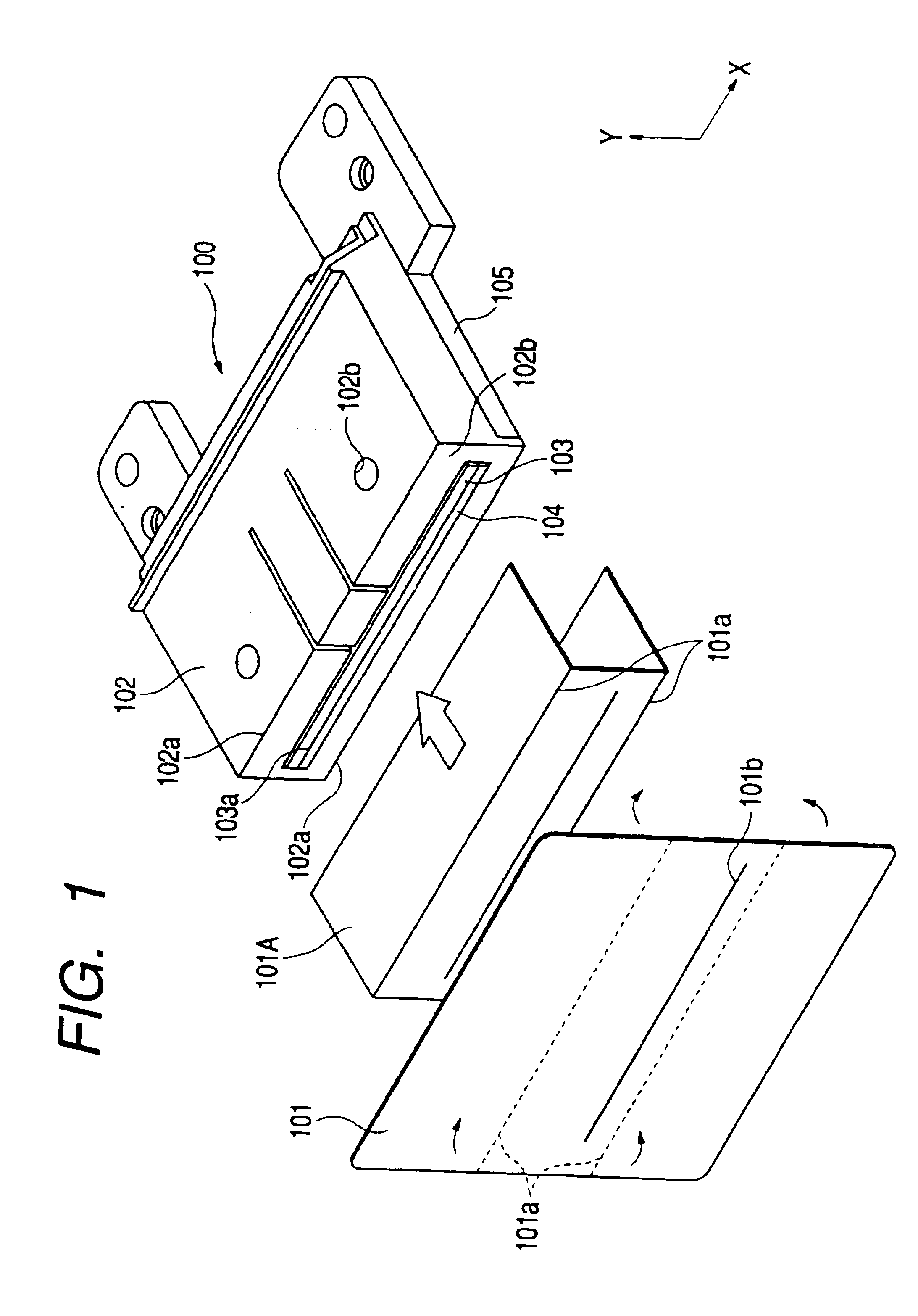
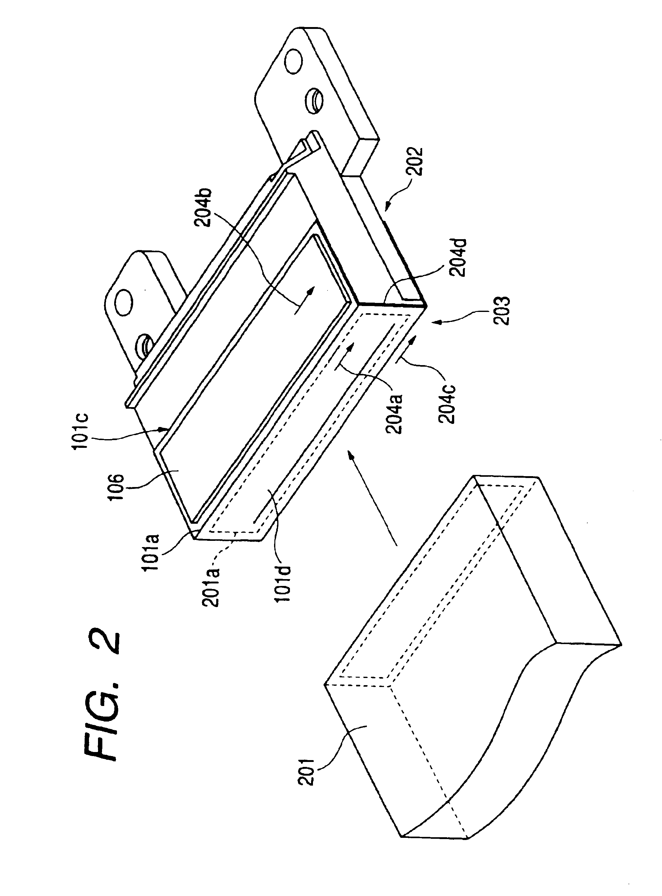
[0140]FIG. 12 is a perspective view which shows the liquid discharge recording head in accordance with a fourth embodiment of the present invention in the state where the orifice plate is separated. FIG. 13 is a cross-sectional view which shows the liquid discharge recording head represented in FIG. 12 in the state where the orifice plate is bonded.

[0141]The orifice plate 101 of the present embodiment is such that the extended portion, which is made longer than the side width (width in the direction X in FIG. 12) of the front plate portion 102b, is formed in the alignment direction of discharge port array 101b. The orifice plate 101 is, therefore, provided with bonding faces to both side faces of the recording head main body 100 in addition to the bonding face to the nozzle opening surface (front plate portion 102b) of the recording head main body 100. The orifice plate 101 bonded to the recording head main body 100 is folded along edge lines on both sides of the ...

fifth embodiment

(Fifth Embodiment)

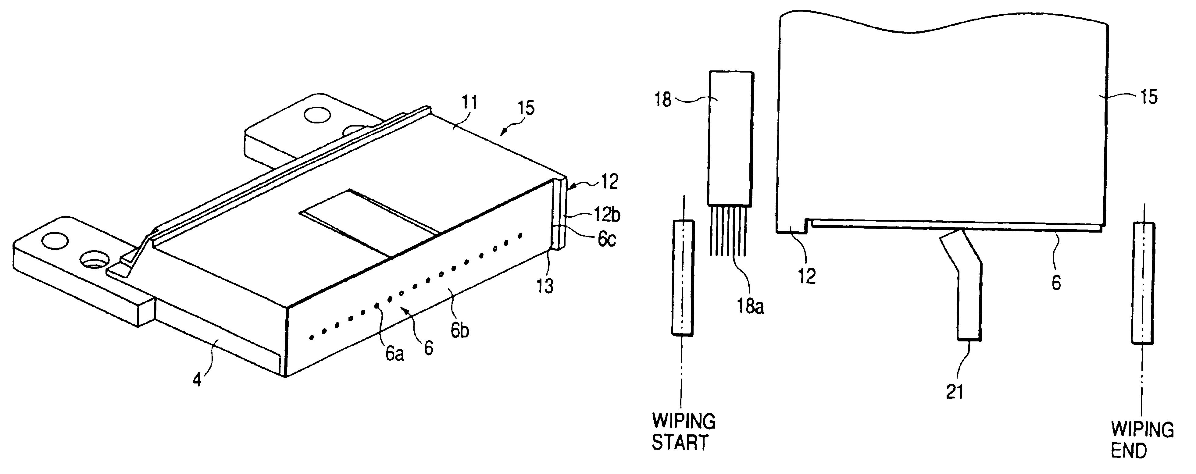
[0145]FIG. 14 is a perspective view which shows the liquid discharge recording head in accordance with a fifth embodiment of the present invention. FIG. 15 is a partially cut off perspective view which shows the state where the orifice plate is separated with the omission of the pressure plate. FIG. 16 is a further exploded perspective view. FIG. 17 is a cross-sectional view which shows this liquid discharge recording head, and FIG. 18 is an enlarged view which shows the principal part thereof represented in FIG. 17, respectively.

[0146]The head main body of liquid discharge recording head of the present embodiment is essentially the same as the conventional example with the exception of extrusion 11d. In other words, as shown in FIG. 15, the heater board (element substrate) 1 is structured by the silicon base plate provided with electrothermal converting elements (discharge heaters) 1a serving as energy generating means, as well as with the wiring which is formed t...


PUM


Abstract

A liquid discharge recording head comprising a recording head main body provided with a plurality of liquid flow paths communicated with a plurality of discharge ports for discharging liquid, respectively, and energy generating means for generating energy utilized for discharging the liquid filled in the liquid flow paths from the discharge ports, and an orifice plate provided with a discharge port array having the plurality of discharge ports aligned in one straight line, and bonded to the front face of the recording head main body having openings of the plurality of discharge ports formed therefor, wherein the orifice plate is provided with the extended portion in the alignment direction of the discharge port array or in the direction orthogonal to the alignment direction, being extended more than the width of the front face of the recording head main body, and the extended portion is fixed to the adjacent face of the front face of the recording head main body.

Description

[0001]This is a divisional application of application Ser. No. 09 / 818,561, filed on Mar. 28, 2001, now U.S. Pat. No. 6,652,062.BACKGROUND OF THE INVENTION[0002]1. Field of the Invention[0003]The present invention relates to a liquid discharge recording head for recording on a recording medium by discharging ink from the discharge port group provided for an orifice plate. The invention also relates to a method of manufacture therefor.[0004]2. Related Background Art[0005]A liquid discharge recording apparatus is such that, for example, ink is supplied to a liquid discharge recording head, and by driving ink droplet discharging means, such as piezoelectric elements or electrothermal converting elements provided for a liquid discharge recording head, in accordance with image data in order to form images on a recording sheet or some other recording medium by means of ink dot patterns. The ink discharge recording apparatus that performs recording by discharging ink from the discharge port...

Claims


Application Information

Patent Timeline
Patent Type & Authority Patents(United States)
IPC IPC(8): B41J2/05B41J2/135B41J2/14B41J2/16B41J2/165B41J2/235
CPCB41J2/14024B41J2/1433B41J2/1601B41J2/1623B41J2/1625B41J2/1626B41J2/1631B41J2/1632B41J2/1634B41J2/1637B41J2002/14362B41J2002/16502
Inventor UMEYAMA, MIKIYAKOIZUMI, YUTAKAYAMAGUCHI, YUKUOFUKAZAWA, HIDEOTAJIMA, HIROKIHATASA, NOBUYUKI
Owner CANON KK
Why Eureka
Try Eureka