Speaker

a speaker and dynamic technology, applied in the field of dynamic speakers, can solve the problems of degrading the electroacoustic conversion efficiency of the speaker, insufficient fixing strength, and inability to achieve separation prevention effect as expected

Inactive Publication Date: 2001-08-30
STAR MICRONICS
View PDF0 Cites 22 Cited by
  • Summary
  • Abstract
  • Description
  • Claims
  • Application Information

AI Technical Summary

Problems solved by technology

However, in the speaker having such a fixing structure, since the large bonding area cannot be obtained, the fixing strength is insufficient.
However, in this case, since a width of a cylindrical magnetic gap G of a ma...

Method used


Image

  • Speaker
  • Speaker
  • Speaker

Examples


Embodiment Construction

[0041] The invention will be described below with reference to the accompanying drawings.

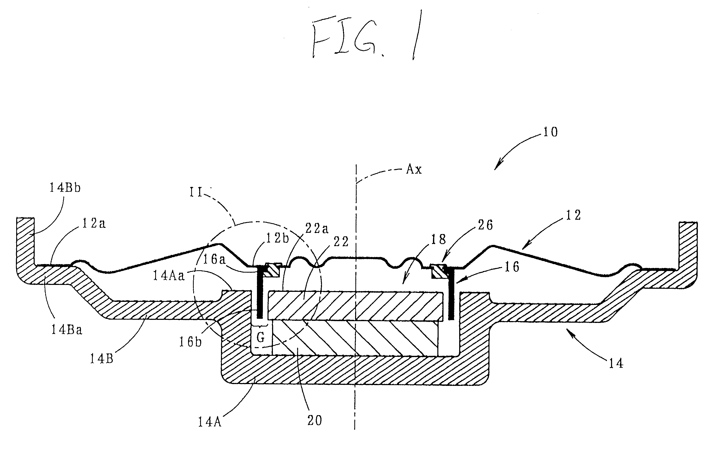
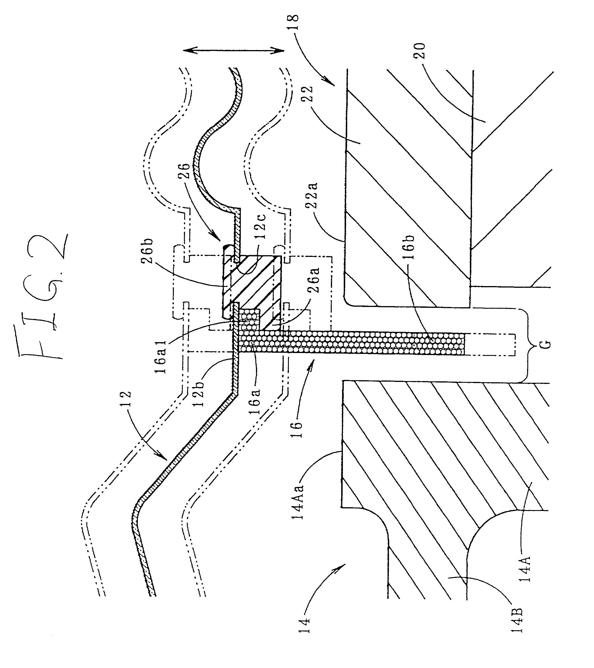
[0042] FIG. 1 is a side sectional view of a speaker 10 according to the embodiment of the invention, in which the speaker faces upward, and FIG. 2 is a detailed diagram of a II portion in FIG. 1.

[0043] As shown in FIG. 1, the speaker 10 is a dynamic speaker comprising a diaphragm 12, a frame 14, a voice coil 16 and a magnetic circuit unit 18. The speaker 10 is a small-sized speaker having an outer diameter of about 30 mm, and used as, for example, a generator of alarm sound or the like, which is mounted on a base plate in a state where it has been stored in a case (not shown) and which is loaded on an automobile or the like.

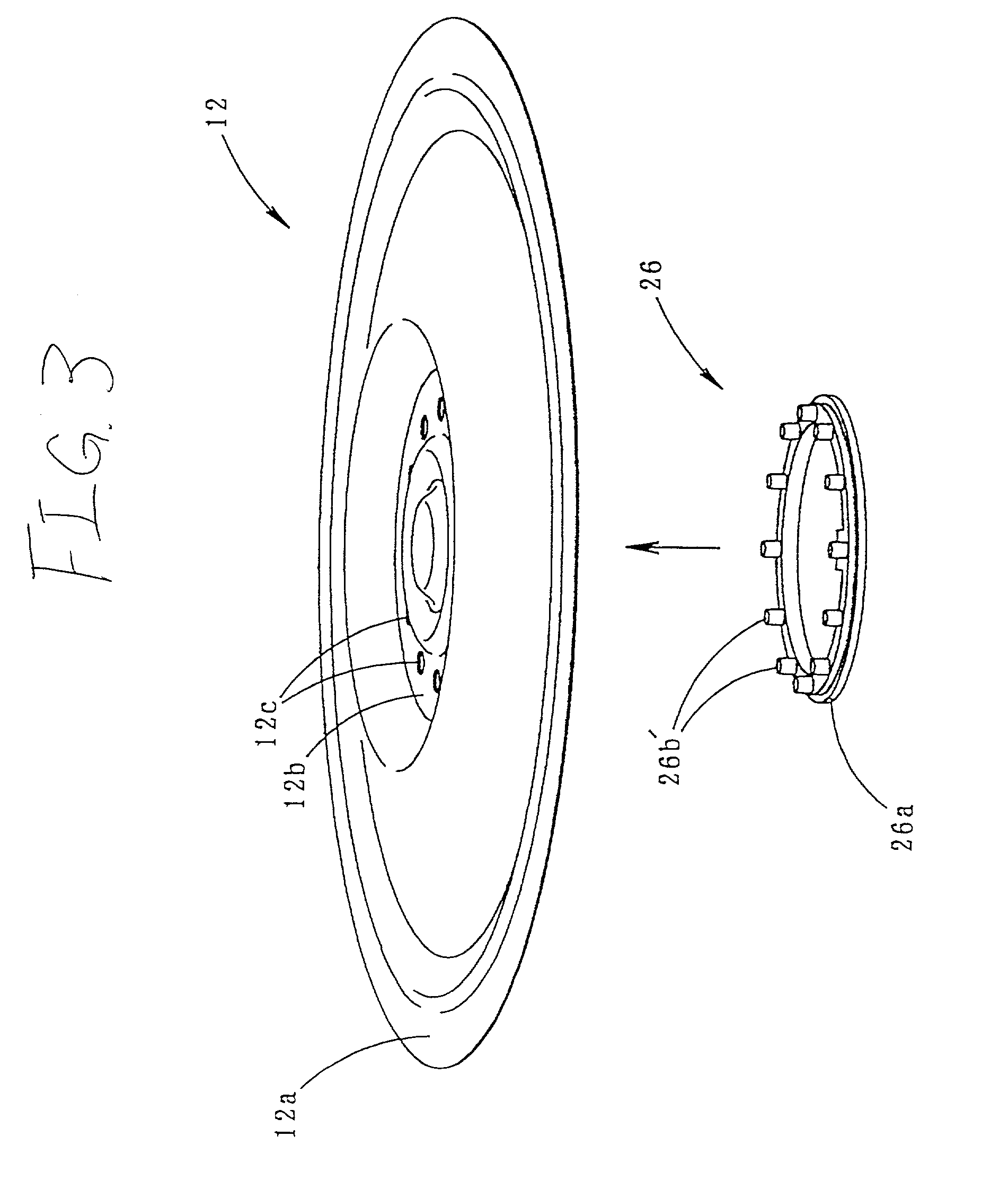
[0044] The diaphragm 12 is a member having a plurality of unevenness formed concentrically, and it is formed by applying heat press molding to a synthetic resin film. A peripheral edge flat portion 12a of the diaphragm 12 and a central flat portion 12b are located on the same...


PUM


Abstract

Fixing of a voice coil 16 to a diaphragm 12 is performed by caulk-fixing a coil supporting member 26 to the diaphragm 12 and by fit-supporting the voice coil 16 by the coil supporting member 26. Hereby, the voice coil 16 is physically fixed to the diaphragm 12 and its fixing strength is heightened. The caulk-fixing is performed by subjecting a caulking projection of the coil supporting member 26 to a plastic deformation thereby to provide a caulk-fixed portion 26b, whereby deformation injurious to the acoustic property does not occur in the diaphragm 12. Further, the fit-supporting is performed by interposing a flange portion 16a1 formed at an upper end portion 16a of the voice coil 16 between an engaging engaging portion 26a of the coil supporting member 26 and a central flat portion 12b of the diaphragm 12 and holding it by them from upper and lower sides.

Description

[0001] 1. Field of the Invention[0002] The present invention relates to a dynamic speaker, and particularly to a structure for fixing a voice coil to a diaphragm in the dynamic speaker.[0003] 2. Description of the Related Art[0004] As one type of a speaker, a dynamic speaker has been known heretofore. The dynamic speaker, as disclosed in, for example, JP-A-6-178390, comprises generally a diaphragm, a voice coil of which one end portion is fixed to the diaphragm, and a magnetic circuit unit defining a cylindrical magnetic gap for placing the other end portion of the voice coil therein.[0005] As the fixing structure of the voice coil to the diaphragm, the following structure is known, as disclosed in the JP publication. One end portion 2a of a voice coil 2 having an I-shaped coiling section as shown in FIG. 10A is bonded and fixed to a diaphragm 4.[0006] However, in the speaker having such a fixing structure, since the large bonding area cannot be obtained, the fixing strength is insu...

Claims


Application Information

Patent Timeline
IPC IPC(8): H04R7/16H04R9/02H04R9/04
CPCH04R9/04
Inventor SUGIYAMA, SHIGERUKITAMURA, HAJIMEFUJINAMI, NAOHIROIMAHORI, YOSHIOYAMASHIMA, HITOSHI
Owner STAR MICRONICS
Why Eureka
Try Eureka