Non-return valve, in particular for medical uses

a non-return valve technology, applied in the field of non-return valves, can solve the problems of delay in valve closure and diaphragm sucking on the support, and achieve the effect of valve closing

Active Publication Date: 2012-10-23
ILLINOIS TOOL WORKS INC
View PDF6 Cites 29 Cited by
  • Summary
  • Abstract
  • Description
  • Claims
  • Application Information

AI Technical Summary

Benefits of technology

[0015]At high pressures, the diaphragm touches the support in the outlet of the nonreturn valve. After the pressure has been relieved, it can happen that the diaphragm stays sucked on the support and delays the closure of the valve. The ribs prevent this sucking and the

Problems solved by technology

After the pressure has been relieved, it can happen that the diaphr

Method used


Image

  • Non-return valve, in particular for medical uses
  • Non-return valve, in particular for medical uses
  • Non-return valve, in particular for medical uses

Examples


Embodiment Construction

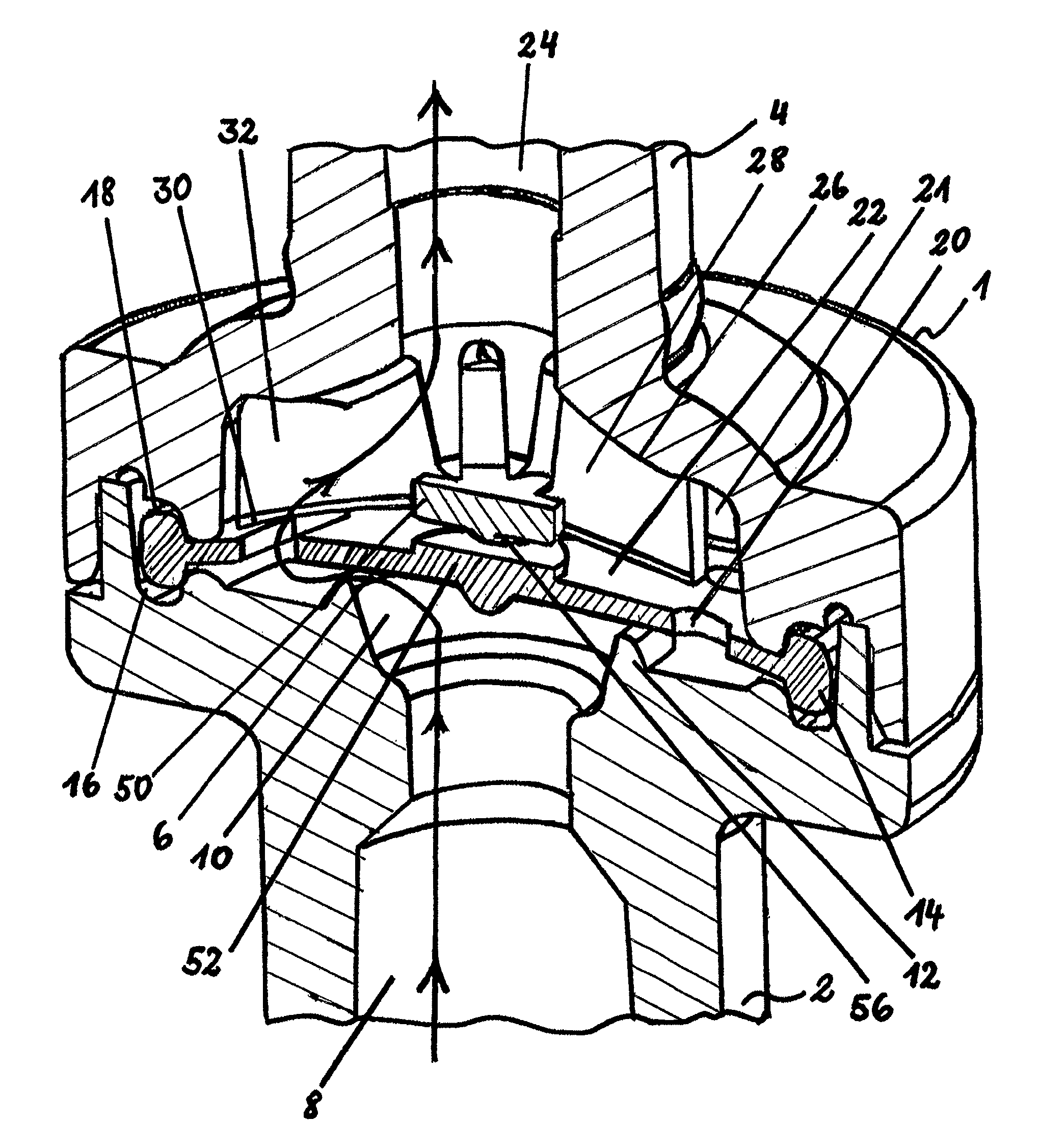
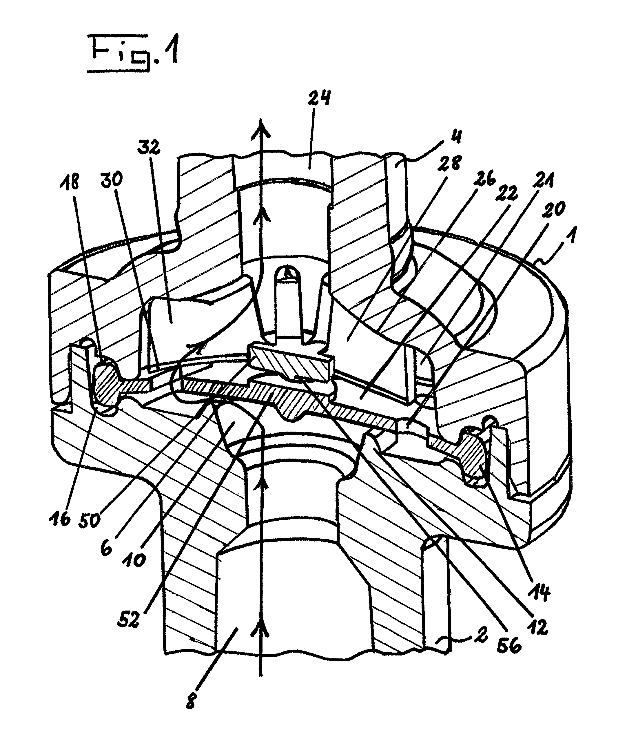
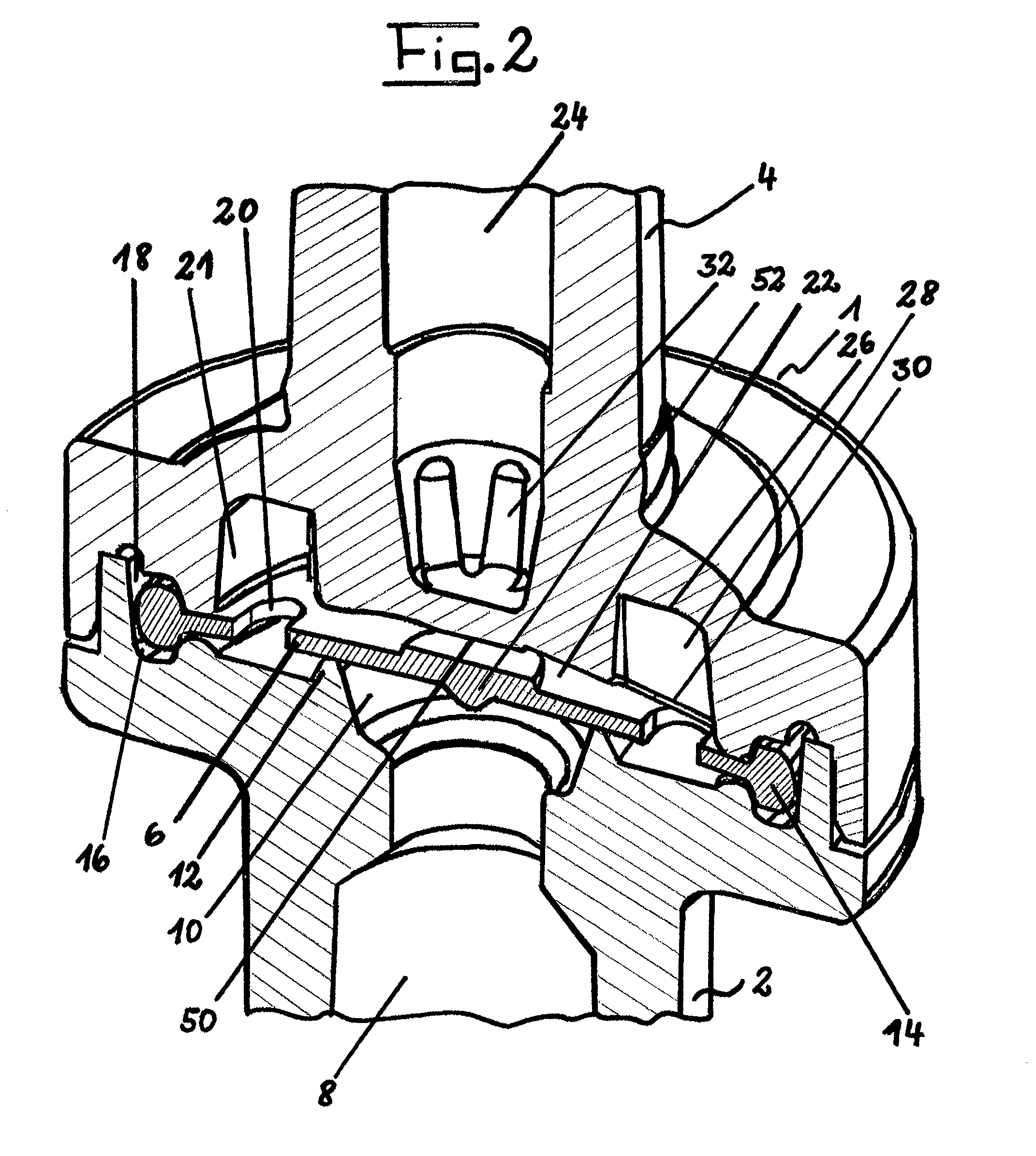
[0021]The nonreturn valve 1 shown greatly enlarged in the drawings is suitable in particular for the field of medicine and can be used, for example, at pressure differences of as low as 0.002 bar. The nonreturn valve 1 is composed of a first tube connection housing 2 and of a second tube connection housing 4, which are preferably produced from plastic by injection molding. A diaphragm disk 6 made from a flexible plastic, for example silicone, is arranged between the two tube connection housings 2 and 4.

[0022]In the first tube connection housing 2, an inlet channel 8 is formed which opens into an inlet chamber 10. The inlet chamber 10 is surrounded by an annular valve seat 12, against which the diaphragm disk 6 is pretensioned.

[0023]The diaphragm disk is designed with a continuously closed central part, which allows considerable tensile forces to be transmitted radially from the inside outward, and vice versa. At its outer peripheral area, the diaphragm disk 6 is provided with an int...


PUM


Abstract

A nonreturn valve includes a first tube connection housing and a second tube connection housing and a diaphragm disk between the first and second tube connection housings. The disk can be lifted from an annular valve seat upon an overpressure in an inlet channel and can be pressed onto the valve seat upon an overpressure in an outlet channel. The diaphragm disk has an annular bead received in mutually opposite annular grooves of the tube connection housings. The diaphragm disk is provided, radially outside the valve seat, with openings leading to an outlet chamber. The second tube connection housing lying opposite the openings is provided with recesses which communicate with the outlet channel and are separated from each other by supporting surfaces for the diaphragm disc. The recesses are connected to the outlet channel by narrow deep grooves.

Description

RELATED APPLICATIONS[0001]The present application is national phase of PCT / EP2008 / 006099 filed Jul. 24, 2008, and claims priority from German Application Number 20 2007 011 322.6 filed Aug. 13, 2007 and German Application Number 20 2007 012 680.8 filed Sep. 11, 2007, the disclosures of which are hereby incorporated by reference herein in their entirety.BACKGROUND[0002]1. Technique Field[0003]The invention relates to a nonreturn valve, in particular for medical uses.[0004]2. Related Art[0005]A nonreturn valve of this type, according to an earlier proposal by the applicant, is known from German utility model 20 2006 016 730.7.[0006]These types of nonreturn valves for the medical field are required in infusion systems, diagnostic equipment, intravenous tube lines and the like, and therefore these types of nonreturn valves have to close in a very reliable manner and the closing time must be only fractions of seconds, in order thereby to avoid any backflow of liquids charged with undesir...

Claims


Application Information

Patent Timeline
IPC IPC(8): F16K15/14
CPCA61M39/24F16K15/144A61M2039/2433A61M2039/246Y10T137/7839Y10T137/7879
Inventor CARMODY, COLMCOSTELLO, KIERAN
Owner ILLINOIS TOOL WORKS INC
Why Eureka
Try Eureka