Transition support system for combustion transition ducts for turbine engines

Inactive Publication Date: 2008-08-28
SIEMENS ENERGY INC
View PDF18 Cites 30 Cited by
  • Summary
  • Abstract
  • Description
  • Claims
  • Application Information

AI Technical Summary

Benefits of technology

[0004]This invention is directed to a transition duct support system for a transition duct that channels hot combustor exhaust gases from a combustor exit to a gas turbine inlet of a turbine engine. The transition duct support system provides a durable support system for supporting a transition duct at an outlet of the duct. The transition duct support system includes a transition support frame configured to retain a transition duct in an aligned position with a gas turbine inlet and in contact with transition exit seals to seal the transition duct to the gas turbine inlet. The transition support frame is configured to absorb axial movement, such as vib

Problems solved by technology

In addition, the welded joints connecting the transition ducts to the turbine inlet experience vibrations throughout ramp up and steady state operating conditions.
The repeated

Method used


Image

  • Transition support system for combustion transition ducts for turbine engines
  • Transition support system for combustion transition ducts for turbine engines
  • Transition support system for combustion transition ducts for turbine engines

Examples


Embodiment Construction

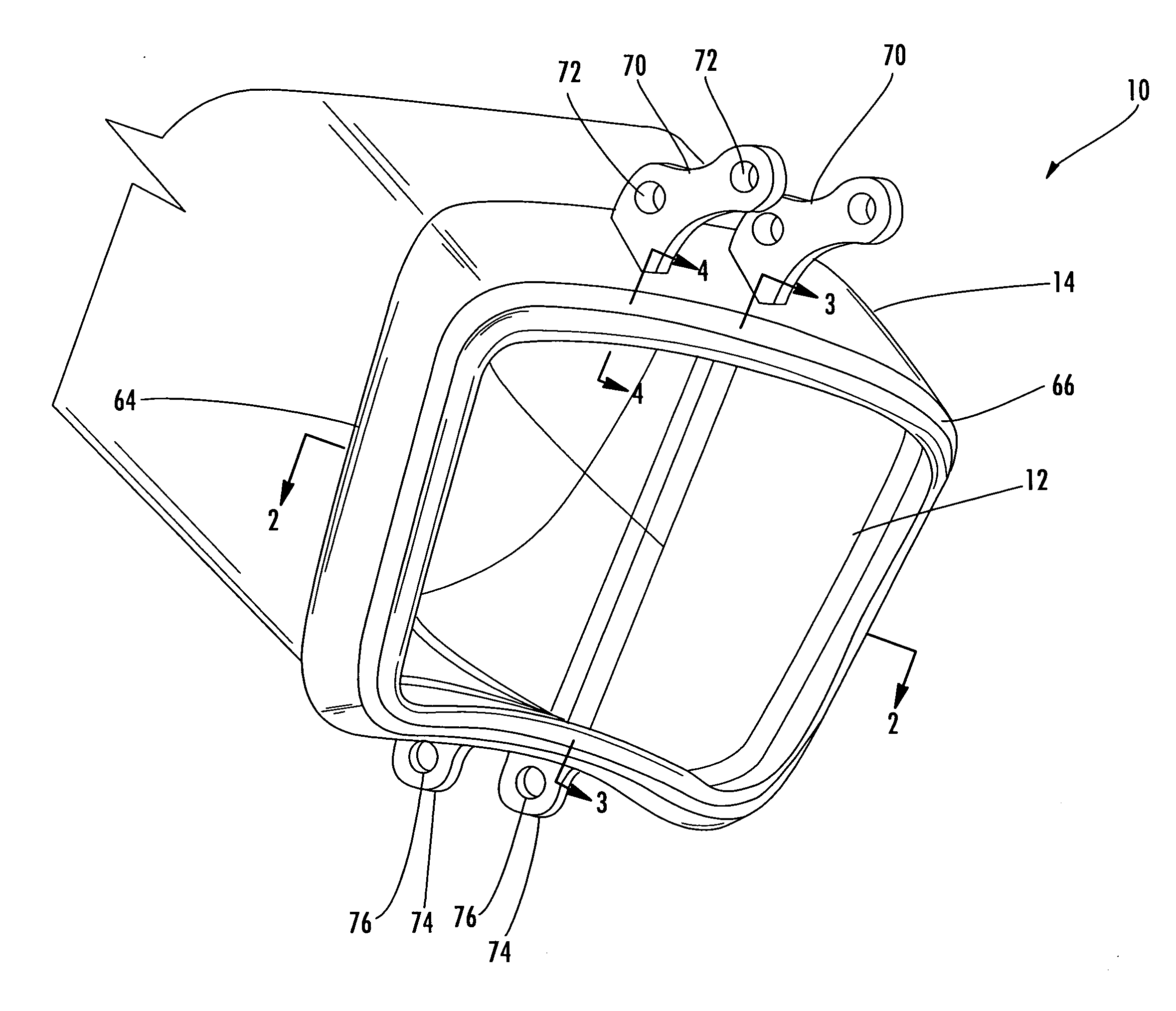
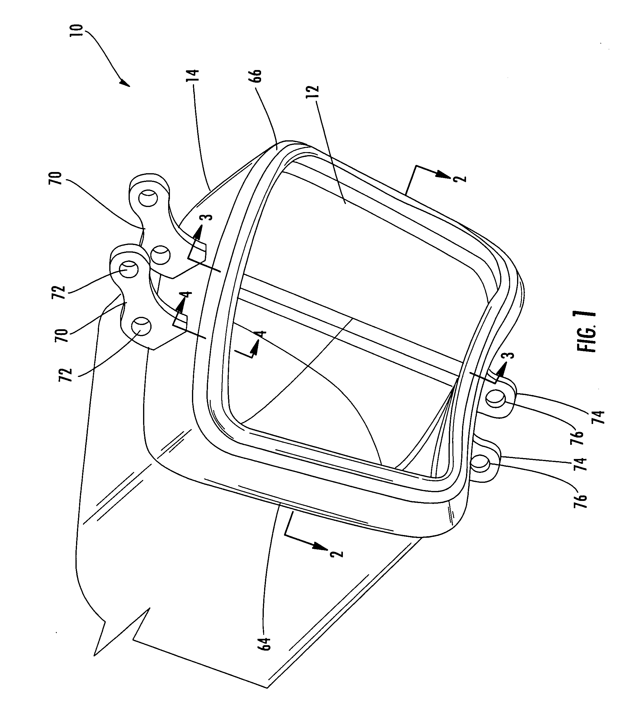
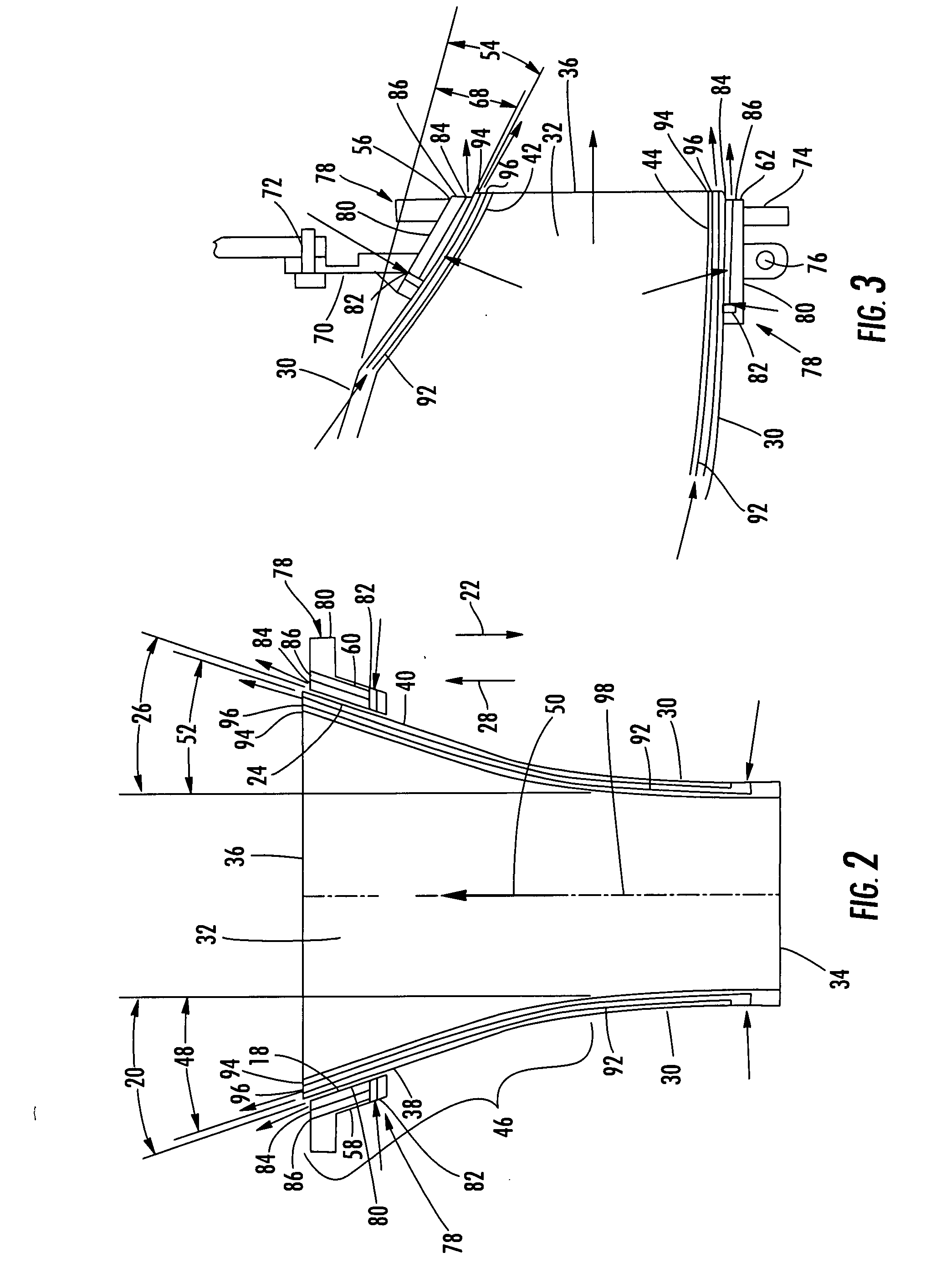
[0022]As shown in FIGS. 1-6, this invention is directed to a transition duct support system 10 for a transition duct 12 that channels hot gases from a combustor exit to a gas turbine inlet 90 of a turbine engine in a can annular combustion system. The transition duct support system 10 provides a durable support system for supporting a transition duct 12 at an outlet 36 of the duct 12. The transition duct support system 10 includes a transition support frame 14 configured to retain a transition duct 12 in an aligned position with a gas turbine inlet 90 and in contact with transition exit seals 16 to seal the transition duct 12 to the gas turbine inlet. The transition support frame 14 is configured to absorb axial movement, such as vibrations, without causing structural damage as is often the case with conventional rigid attachments, such as welds. The transition support frame 14 may include a first inner surface 18 positioned at an oblique angle 20 for preventing axial movement in a ...


PUM


Abstract

A transition duct support system for a transition duct that channels hot gases from a combustor exit to a gas turbine inlet of a turbine engine. The transition duct support system includes a transition support frame formed from a body positioned around a transition duct body at an outlet transition section. The transition support frame may include a first inner surface aligned with and positioned proximate to portion of the outlet transition section that is positioned at an oblique angle relative to the outer wall of the transition duct body to limit linear movement of the transition duct body in a first direction. The transition support frame may also include a second inner surface positioned at an oblique angle to limit linear movement of the transition duct body in a second direction opposite the first direction.

Description

FIELD OF THE INVENTION[0001]The invention relates in general to combustion turbine engines and, more specifically, to transition ducts for routing combustor exhaust gas flow from combustors to a turbine assembly of a combustion turbine engine.BACKGROUND OF THE INVENTION[0002]Typically, gas turbine engines include a compressor for compressing air, a combustor for mixing the compressed air with fuel and igniting the mixture, and a turbine blade assembly for producing power. Transition ducts extend between a combustor and a turbine blade assembly to direct combustor gases through the turbine blade assembly to impart rotational movement on the rotor of the turbine blade assembly. Conventional transition ducts are typically formed from a plenum that requires support from more rigid mounting support structure at the exit that is welded to the plenum. The rigid support structure is used for affixing the transition assembly to the turbine inlet. This rigid support structure is also used to ...

Claims


Application Information

Patent Timeline
IPC IPC(8): F02C7/20
CPCF01D9/023F02C7/28F01D25/12F01D11/005
Inventor SUTCU, MAZYOUNGBLOOD, BRADLEY T.DAWSON, ROBERT W.MORAES, RICARDO F.ZBOROVSKY, JAMES M.
Owner SIEMENS ENERGY INC
Why Eureka
Try Eureka