Keyswitch and keyboard capable of showing movement depth

Active Publication Date: 2018-05-17
PIXART IMAGING INC
View PDF1 Cites 18 Cited by
  • Summary
  • Abstract
  • Description
  • Claims
  • Application Information

AI Technical Summary

Benefits of technology

[0010]The keyswitch and the related keyboard of the present invention utilize the multistage positioning component to be cooperated with the actuating portion of the keycap to provide the feedback function of showing the movement depth. The multistage positioning component can be the elastic piece structure having the free end for wavy motion, or the elastic piece structure having the two opposite ends fixed on the wall and the middle part capable of being twisted and deformed, or the electrode terminal utilizing conductive current to form the feedback signal. The multistage positioning component with an elastic piece form generates the feedback signal according to the rebounding force or the rebounding sound, so that the user or the processing unit can identify the movement depth of the keyswitch. The multistage positioning component can define the number of feedback stages by v

Problems solved by technology

However, the conventional mechanical keyswitch 70 utilizes the lifting unit designed as a compression spring to provide the resilient recovering force, the user merely feel one-stage hand feeling wi

Method used


Image

  • Keyswitch and keyboard capable of showing movement depth
  • Keyswitch and keyboard capable of showing movement depth
  • Keyswitch and keyboard capable of showing movement depth

Examples


first embodiment

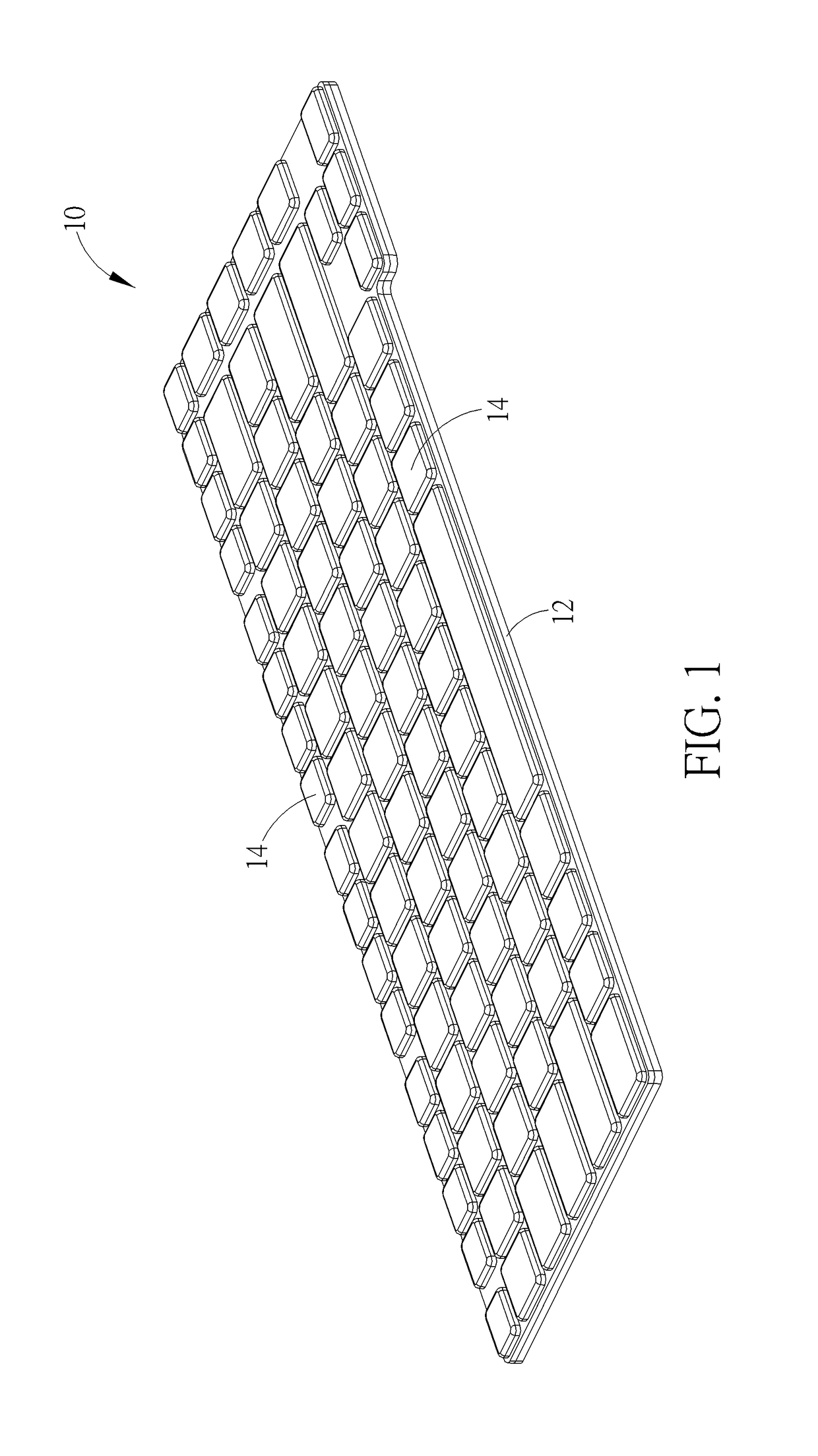
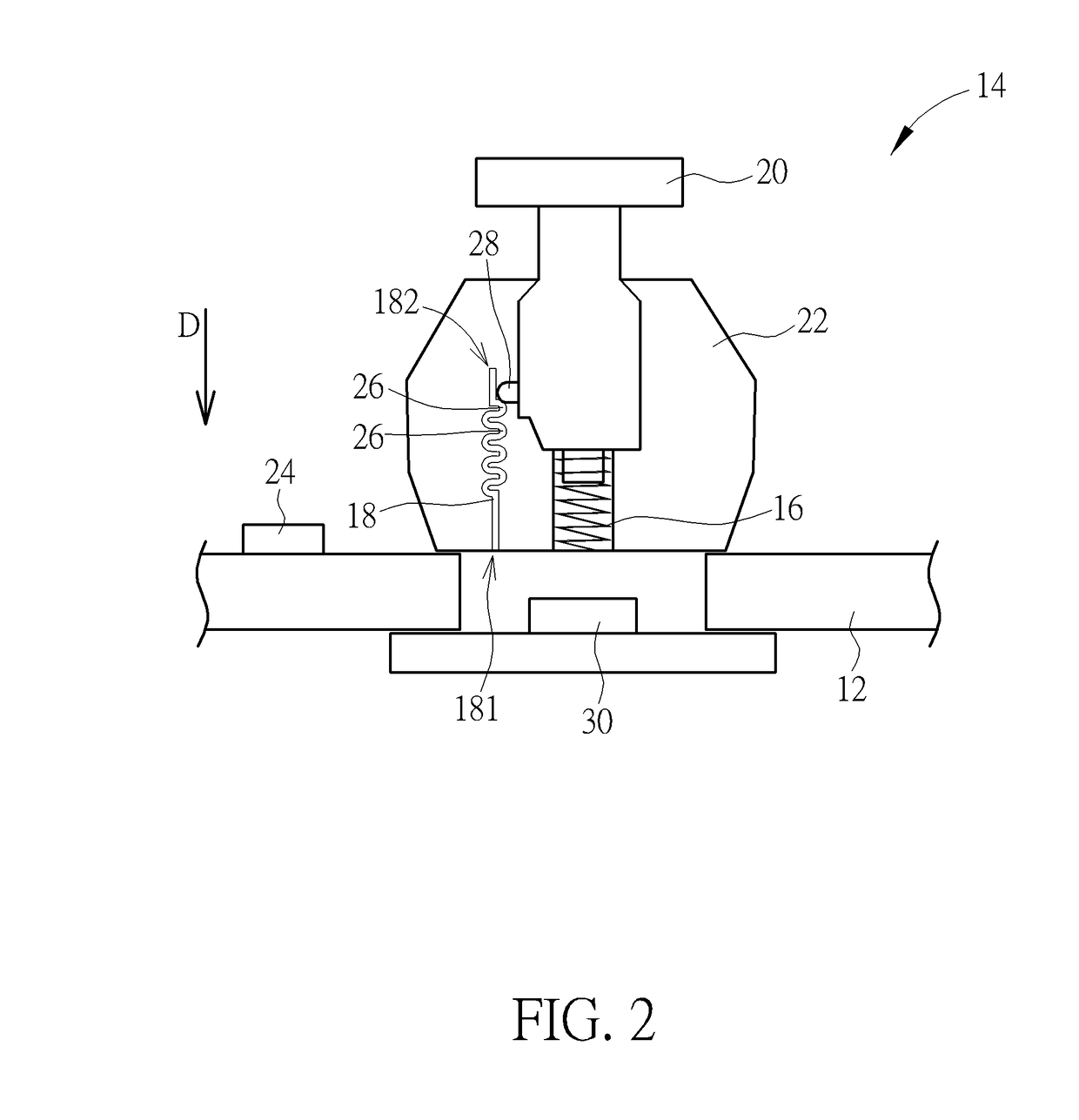
[0018]Please refer to FIG. 1 to FIG. 3. FIG. 1 is a structural diagram of a keyboard 10 according to an embodiment of the present invention. FIG. 2 and FIG. 3 respectively are structural diagrams of a keyswitch 14 in different operation modes according to the present invention. The keyboard 10 includes a substrate 12 and a plurality of keyswitches 14, and the plurality of keyswitches 14 is arranged on the substrate 12 in sequence. At least one or more keyswitches 14 of the plurality of keyswitches 14 can include a lifting unit 16, a multistage positioning component 18, a keycap 20, a supporting component 22 and a processing unit 24. The lifting unit 16, the multistage positioning component 18, the supporting component and the processing unit 24 are respectively disposed on corresponding positions of the substrate 12. The multistage positioning component 18 preferably includes a plurality of first actuating portions 26. A lower portion of the keycap 20 is partly disposed inside the s...

second embodiment

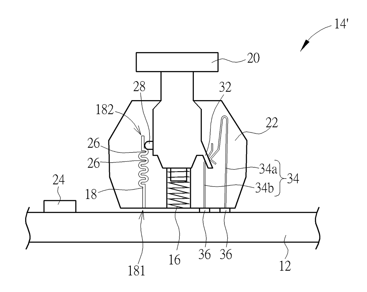
[0022]The optical keyswitch is an example of the above-mentioned embodiment, and actual application can be varied accordingly. The multistage positioning component of the keyswitch is further suitable for a mechanical keyswitch. Please refer to FIG. 4. FIG. 4 is a structural diagram of a keyswitch 14′ according to the present invention. The keyswitch 14′ further includes an actuating portion 32 and a resilient conductive component 34, the actuating portion 32 is disposed under the lower portion of the keycap 20, and the resilient conductive component 34 is disposed inside the supporting component 22 and contacts against a conductive terminal 36 of the substrate 12. While the keycap 20 is not pressed, two parts 34a and 34b of the resilient conductive component 34 are separated. While the keycap 20 is pressed downwardly, the actuating portion 32 drives resilient deformation of the resilient conductive component 34 to contact the part 34a with the part 34b, and an actuating signal is o...

third embodiment

[0023]Please refer to FIG. 5. FIG. 5 is a structural diagram of the keyswitch 38 according to the present invention. Two opposite ends of the multistage positioning component 18′ of the keyswitch 38 are respectively disposed on an inner wall of the supporting component 22. The supporting component 22 can be a housing structure with any form, the two opposite ends 18a′ of the multistage positioning component 18′ are fixed on the inner wall of the housing structure, and a middle part (the part except the ends 18a′, which means the part where on the plurality of first actuating portions 26 is disposed) of the multistage positioning component 18′ does not contact against or is not adhered to the inner wall of the housing structure preferably. A tiny interval is formed between the inner wall and the plurality of first actuating portions 26 for being buffer space while the multistage positioning component 18′ is resiliently deformed. When the keycap 20 is pressed, the second actuating por...


PUM


Abstract

A keyboard has a keyswitch capable of showing its movement depth. The keyswitch includes a substrate, a lifting unit, a multistage positioning component and a keycap. The lifting unit is disposed on the substrate. The multistage positioning component is disposed on the substrate and has a plurality of first actuating portions. The keycap is connected with the lifting unit and adjacent by the multistage positioning component. The keycap has a second actuating portion. The keycap is moved relative to the substrate via the lifting unit, and the second actuating portion can contact against one of the plurality of first actuating portions to generate a feedback signal.

Description

BACKGROUND OF THE INVENTION1. Field of the Invention[0001]The present invention relates to a keyswitch and a keyboard, and more particularly, to a keyswitch and a keyboard capable of showing its movement depth.2. Description of the Prior Art[0002]Please refer to FIG. 7. FIG. 7 is a structural diagram of a mechanical keyswitch 70 in prior art. A keycap 72 and a related lower stretching portion of the conventional mechanical keyswitch 70 are movably disposed inside a supporter 74, and the keycap 72 can be moved relative to the supporter 74 via a lifting unit 76. While the keycap 72 is pressed to move downwardly along the supporter 74, a first resilient component 78 is resiliently deformed to contact a second resilient component 80 for forming a conductive channel and outputting an actuating signal, and the actuating signal is analyzed to acquire a control command about the pressed mechanical keyswitch 70. However, the conventional mechanical keyswitch 70 utilizes the lifting unit desi...

Claims


Application Information

Patent Timeline
IPC IPC(8): H01H13/85H01H3/12
CPCH01H13/85H01H2215/028H01H3/125H01H13/803H01H2215/03H01H2235/00H01H2239/022H01H15/102
Inventor WANG, TSUNG-FAKUO, SHIH-WEI
Owner PIXART IMAGING INC
Why Eureka
Try Eureka