Positively balancing an armature

a positive balancing and armature technology, applied in the field of positive balancing an armature, can solve the problems of process-induced contamination, weakening of the carrier material, and disadvantage of the balancing principle, and achieve the effect of reducing the risk of affecting the stability of the armature and reducing the risk of affecting the balancing

Inactive Publication Date: 2018-05-17
RAUSCH & PAUSCH
View PDF0 Cites 6 Cited by
  • Summary
  • Abstract
  • Description
  • Claims
  • Application Information

AI Technical Summary

Benefits of technology

[0010]It is hence an object of the present invention to propose a method which makes it possible with little technical effort to carry out a balancing of an internal armature or to prepare the balancing already in the production process of the internal armature. It is necessary here that for balancing the balancing elements can be placed with simple technical means and additionally are fixed so rigidly that the balancing elements are permanently connected with the structural group to be balanced. It is further an object of the

Problems solved by technology

Negative balancing causes process-induced contamination, because material is removed and therefore detached.
With regard to cleanness upon assemblage this balancing principle is hence of disadvantage.
According to conventional methods it is particularly disadvantageous that, for example, with negative balancing during a milling or drilling process the removed material can penetrate the structural group such that contaminations result therefrom which disturb the operation of the electric motor.
Furthermore, a weakening of the carrier material may have to be taken into account, because mass is removed from components which in particularly disadvantageous methods are unstable with regard to a force acting thereon.
Moreover, it is particularly disadvantageous that corresponding processing steps for milling or drilling are carried out during the balancing process and are not carried out already at the time of production of the electric motor.
Moreover, the milling of material is typically irreversible.
With positive balancing there occurs the probl

Method used


Image

  • Positively balancing an armature
  • Positively balancing an armature
  • Positively balancing an armature

Examples


Embodiment Construction

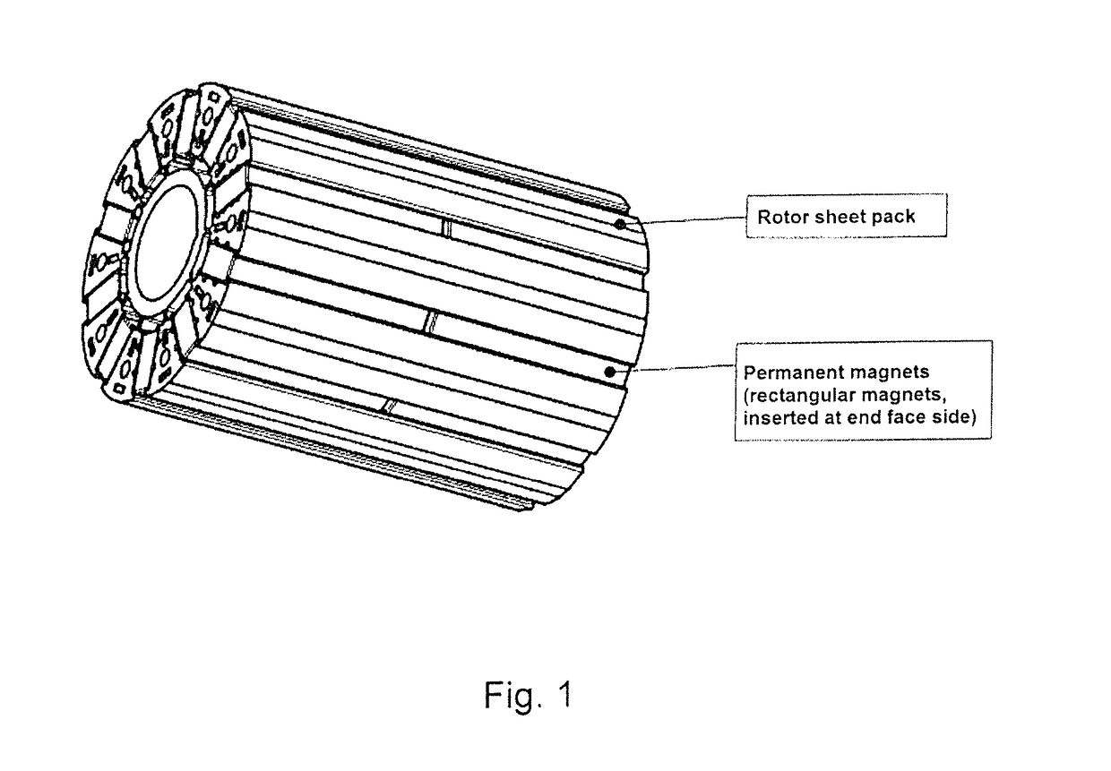
[0044]FIG. 1 shows a rotor sheet pack equipped with permanent magnets, in the present case with rectangular magnets which are inserted on the end face side. Therefore, in the present rotor sheet pack there is drawn the end face on the left and on the right. The rotor sheet pack serves as an initial part for overmolding and configuring the plastic overmolding such that on one or on both end faces of the rotor sheet pack there are shaped recesses for receiving balancing elements. Here, it is particularly advantageous that the rotor sheet pack shown in FIG. 1 can be configured as a conventional rotor sheet pack.

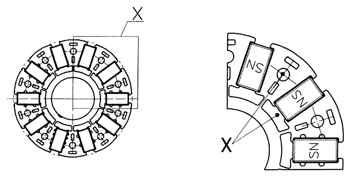
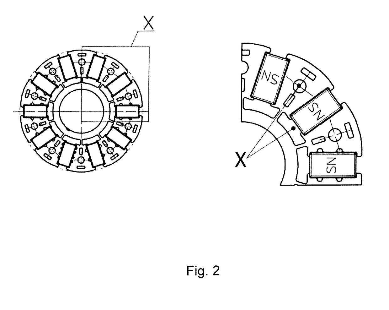
[0045]FIG. 2 shows on the left side a rotor sheet pack equipped with permanent magnets, which is explained more closely in a detail view according to the section X. In particular the detail on the right side shows, by means of the drawn lines, the longitudinal openings through the rotor sheet pack, into which the plastic is injected later. The injecting is, according to an aspec...


PUM

PropertyMeasurementUnit
Dimensionaaaaaaaaaa

Abstract

A method for producing a positively balanceable internal armature to be used in an electric motor, in particular a direct-current electric motor, which makes it possible that the structural group is configured such that a balancing of the internal armature can take place with little technical effort. A manufacturing apparatus which is arranged to execute the proposed method or which can be operated by the proposed method. Further, an internal armature to be used in an electric motor as well as to the electric motor itself. Further, a computer program product is proposed, having control commands which implement the proposed method or operate the proposed manufacturing apparatus.

Description

FIELD[0001]The present invention is directed to a method for producing a positively balanceable internal armature to be used in an electric motor, in particular a direct-current electric motor, which method makes it possible that the structural group is configured such that a balancing of the internal armature can take place with particularly little technical effort and particularly cleanly. The invention is further directed to a manufacturing apparatus which is arranged to execute the proposed method or which can be operated by means of the proposed method. Further, the present invention is directed to an internal armature to be used in an electric motor as well as to the electric motor itself. Further, a computer program product is proposed, having control commands which implement the proposed method or operate the proposed manufacturing apparatus.BACKGROUND[0002]DE 10 2013 013 650 A1 shows a rotatably mounted rotation body, in particular a fan wheel with a device for balancing, c...

Claims


Application Information

Patent Timeline
IPC IPC(8): H02K15/16H02K15/12H02K15/03H02K1/27H02K1/28B29C45/14
CPCH02K15/165H02K15/12H02K15/03H02K1/276H02K1/28B29C45/14336B29K2101/12B29L2031/7498H02K7/04
Inventor FLEISCHMANN, ERNSTKEMNITZ, ROCCO
Owner RAUSCH & PAUSCH
Why Eureka
Try Eureka