Method and Device for Strapping Goods

a technology for strapping goods and goods, applied in the direction of arc welding apparatus, resistance welding apparatus, application, etc., can solve the problems of reducing the service life of the connection, requiring additional sealing elements, and limiting the load capacity of such connections, so as to reduce the technical and logistical complexity, the cross-section of the welding cable(s) is not excessively large, and the effect of high operational reliability

Inactive Publication Date: 2008-11-27
SIGNODE IND GRP GMBH
View PDF6 Cites 15 Cited by
  • Summary
  • Abstract
  • Description
  • Claims
  • Application Information

AI Technical Summary

Benefits of technology

[0018]The spot-welding procedure of disclosed embodiments of the present invention may be used at little technical and logistic complexity while nevertheless offering high operational reliability. This technical problem is solved by strapping equipment which is characterized in that the sealing system is a resistance welder which comprises at least two electrodes that may be hooked up to a power source and at least one piercing element allowing piercing the protective layer of at least one of the strap plies in order to thereby allow electrical contact between the metal band and the piercing element.
[0019]In another aspect of the present invention, having independent significance, the strapping equipment includes a module usually termed “strapping head”. All those mechanical components, or a part of them, which are required to advance the strap, to generate the strap tension, to seal the strap during production of the seal, to cut off the strap and to implement the seal, may be combined compactly in this strapping head. In accordance with disclosed embodiments of the present invention, an electric power element of the resistance welder preferably shall be configured as a whole immediately next to electrode members of the resistance welder. This configuration offers the advantage in particular that one or more welding cables between said power element and the minimum of one electrode member may be kept short and the cross-section of the welding cable(s) need not be excessively large. Moreover electric losses are reduced thereby and cooling shall be minimized.

Problems solved by technology

This procedure however incurs the drawback of requiring an additional sealing element, typically a lead seal.
Moreover this kind of seal may not always withstand high stresses.
This procedure however may be considered disadvantageous in that an inert gas must be used to for seal.
However the ensuing restricted load capacity of such connections and the relatively large area of damage to the said protective layer and to the metal strap may be considered disadvantageous.
At that time only uncoated steel straps were used, consequently the objective of the German patent document 929 059 has been inappropriate to packing straps fitted with a protective coating.
However the coatings of the packing straps also always are an impediment in such welding procedures, they ought to be considered basically inappropriate.

Method used


Image

  • Method and Device for Strapping Goods
  • Method and Device for Strapping Goods
  • Method and Device for Strapping Goods

Examples


Embodiment Construction

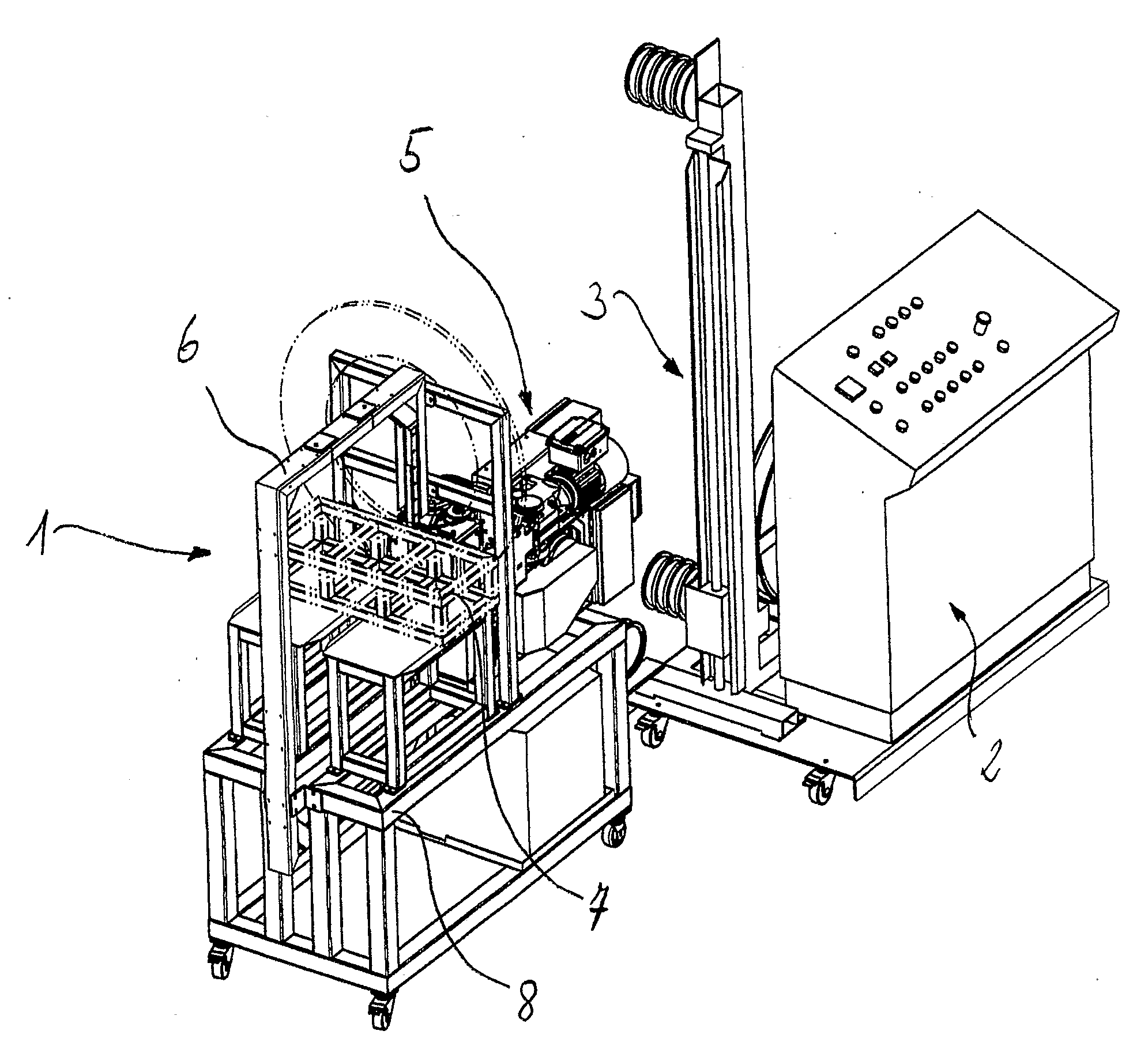
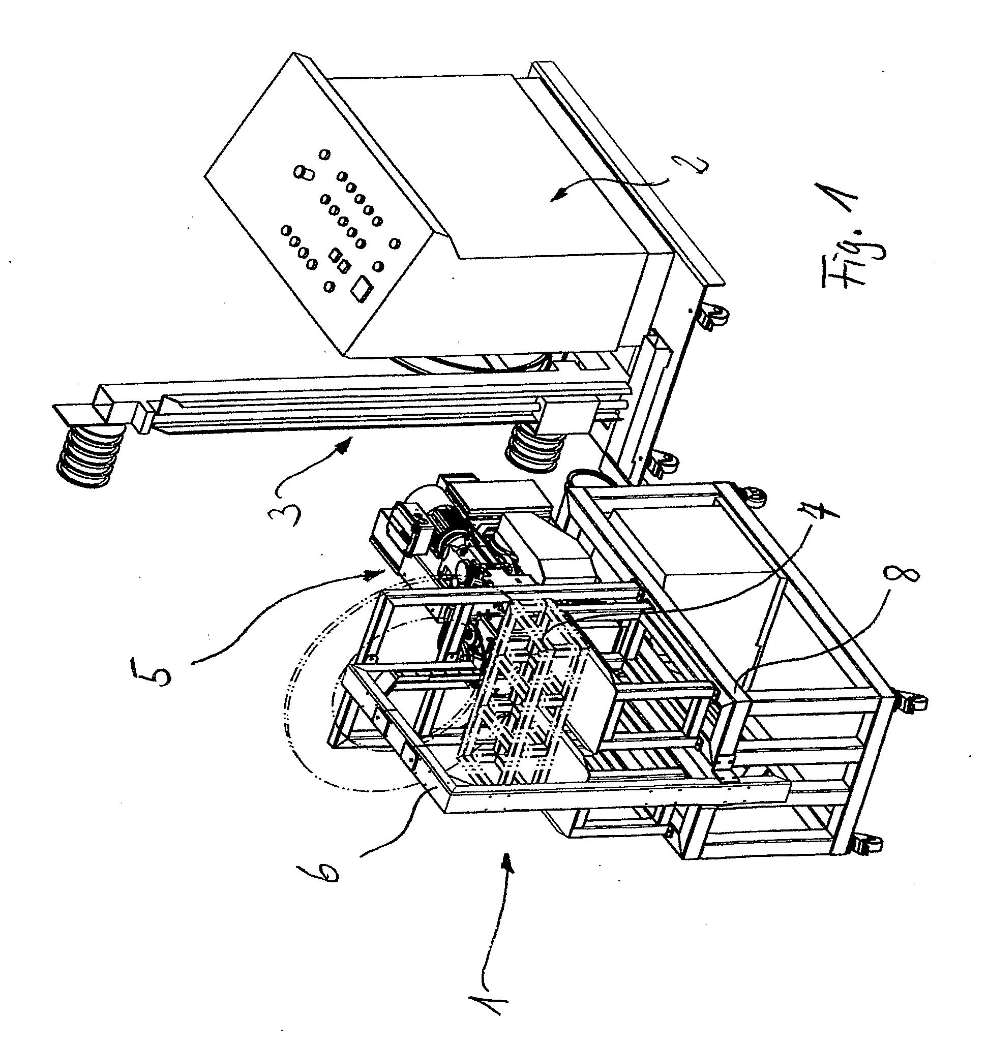
[0031]FIG. 1 shows strapping equipment 1 comprising a control console 2, a supply receptacle 3 to store and to dispense the packing strap, a strapping head 5 to advance said strap, to tension a strap loop and further to implement a packing strap seal. Moreover the strapping equipment is fitted with a strap guide 6 whereby the strap is automatically moved by the machine along a predetermined path on and around a package 7. All components except the strapping head 5 are conventional in strapping equipment.

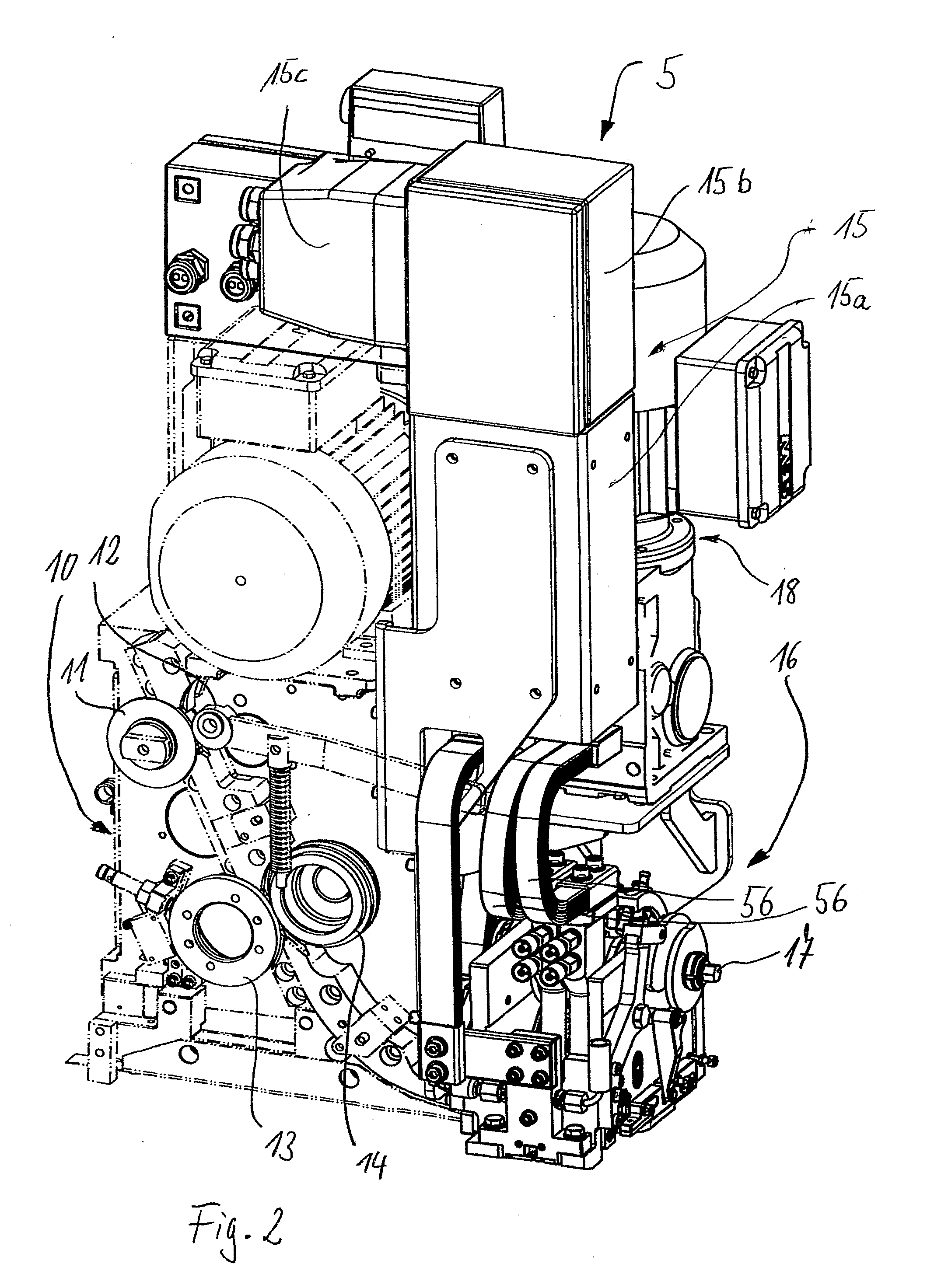
[0032]The strapping head 5 is mounted jointly with the guide 6 on a framework 8 and shown separately in FIG. 2, and also comprises a strap drive 10 known per se. Said drive may be fitted with in particular with one or several pairs of rollers 11, 12; 13, 14 and optionally with further individual deflection rollers of which at least one is motor driven to advance or pull back the strap, which is guided between said rollers.

[0033]A welding and clamping unit 16 is integrated into the st...


PUM

PropertyMeasurementUnit
electric poweraaaaaaaaaa
resistanceaaaaaaaaaa
load resistanceaaaaaaaaaa

Abstract

In a method to seal/lock a strap (44) including a metal strap (44d) which is fitted at least in the zone of seal with a protective layer (44c), the packing strap is laid in the form of a loop around the package and is held, in particular, clamped, in place before and/or during production of the seal. The seal is implemented on the packing strap (44) by resistance welding and the protective layer (44c) of the packing strap (44) shall be pierced before and/or during production of the seal.

Description

TECHNICAL FIELD[0001]The disclosure relates to a method creating an seal for a packing (looping) strap fitted with a metal strap, in particular a metal steel strap, said strap being fitted with a protective coat at least in the zone of said seal, the packing strap being emplaced in the form of a strap loop around the package and being kept in place in a predetermined manner prior to and / or during the creation of said seal, for instance being clamped in place by at least one strap clamp. The disclosure also relates to strapping equipment to strap a package and comprising a metal packing strap fitted with a protective coating, said equipment being fitted with a sealing device to create a seal allowing joining together two superposed strap plies of a packing strap loop.BACKGROUND[0002]To appropriately ship packages, it has long been known to strap such packages with one or several packing straps that are sealed by strapping equipment to said packages. To ship heavy-industry goods, usua...

Claims


Application Information

Patent Timeline
Patent Type & Authority Applications(United States)
IPC IPC(8): A01F15/14B23K9/28
CPCB23K11/115B23K11/163B65B13/32B23K11/16B65B11/32
Inventor TAKIDIS, DIMITRIOSFINZO, FLAVIOADERHOLD, HARRY
Owner SIGNODE IND GRP GMBH
Why Eureka
Try Eureka