

Molding die projection mechanism and molding die comprising same projection mechanism
- Summary
- Abstract
- Description
- Claims
- Application Information
AI Technical Summary
Benefits of technology
Problems solved by technology
Method used
Image

Examples
Embodiment Construction
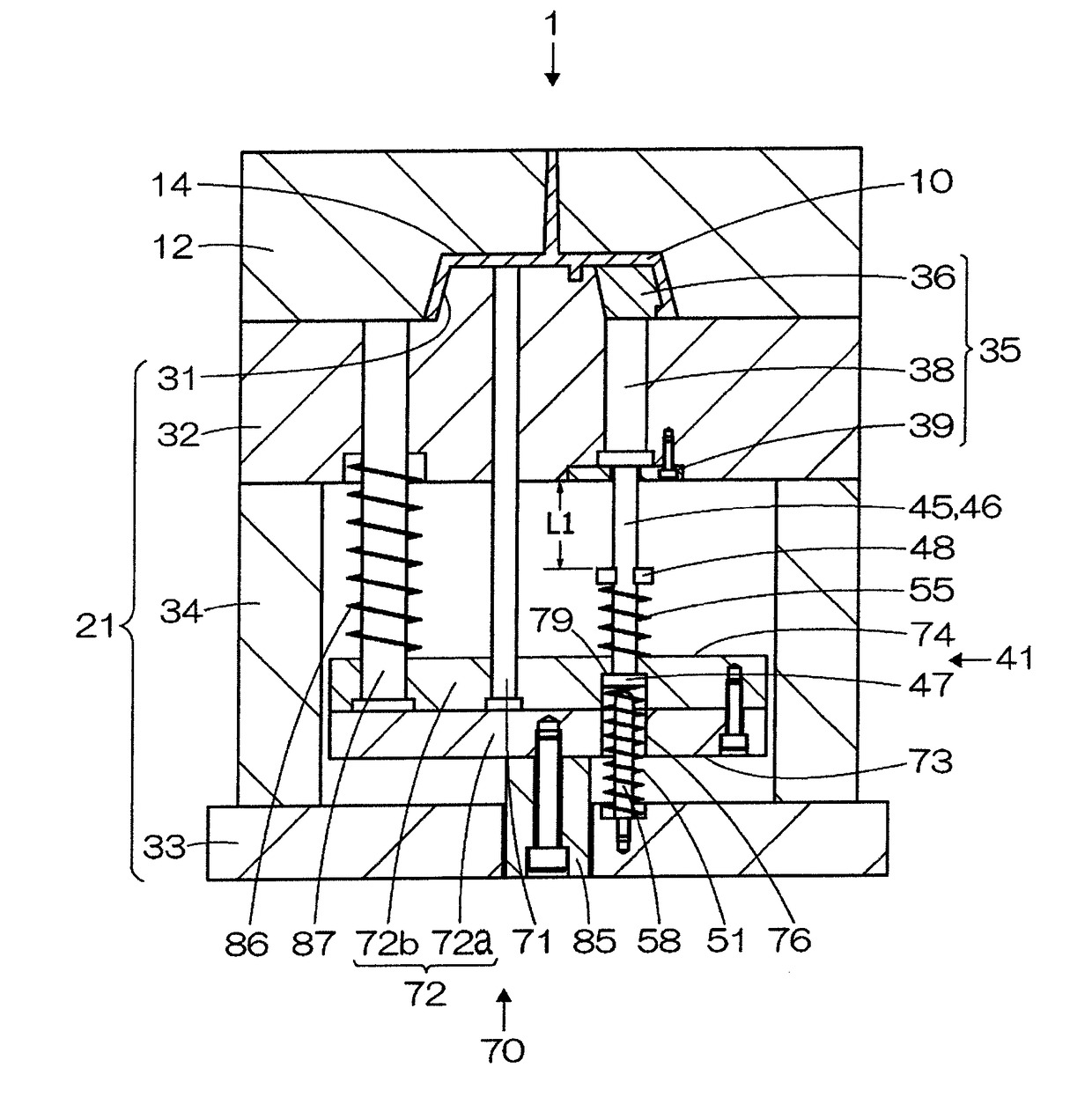
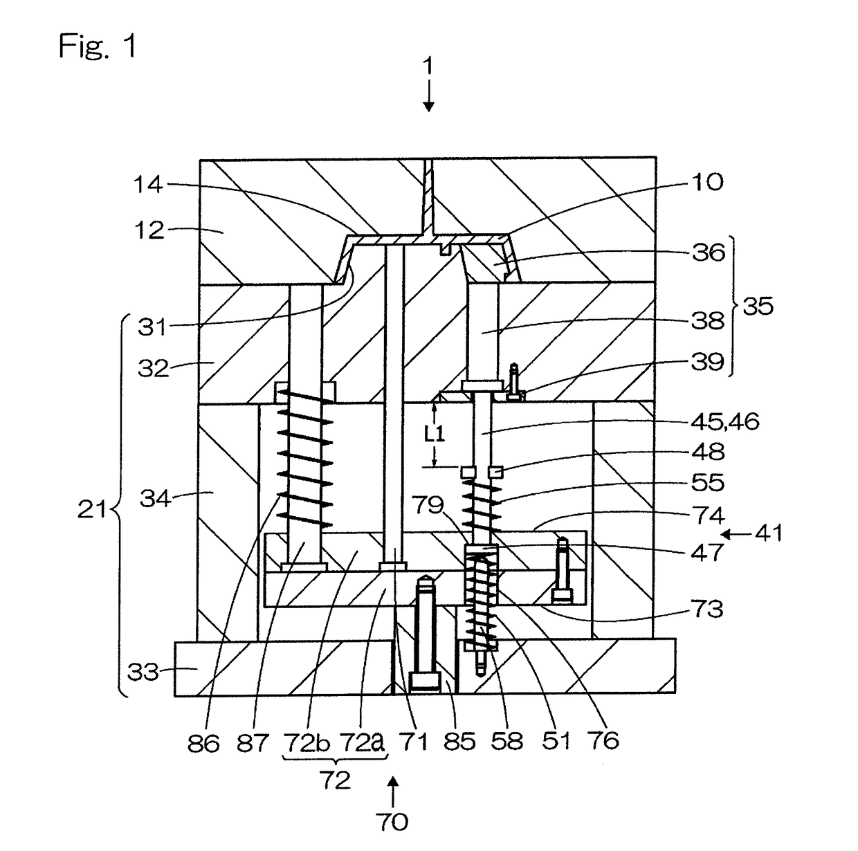
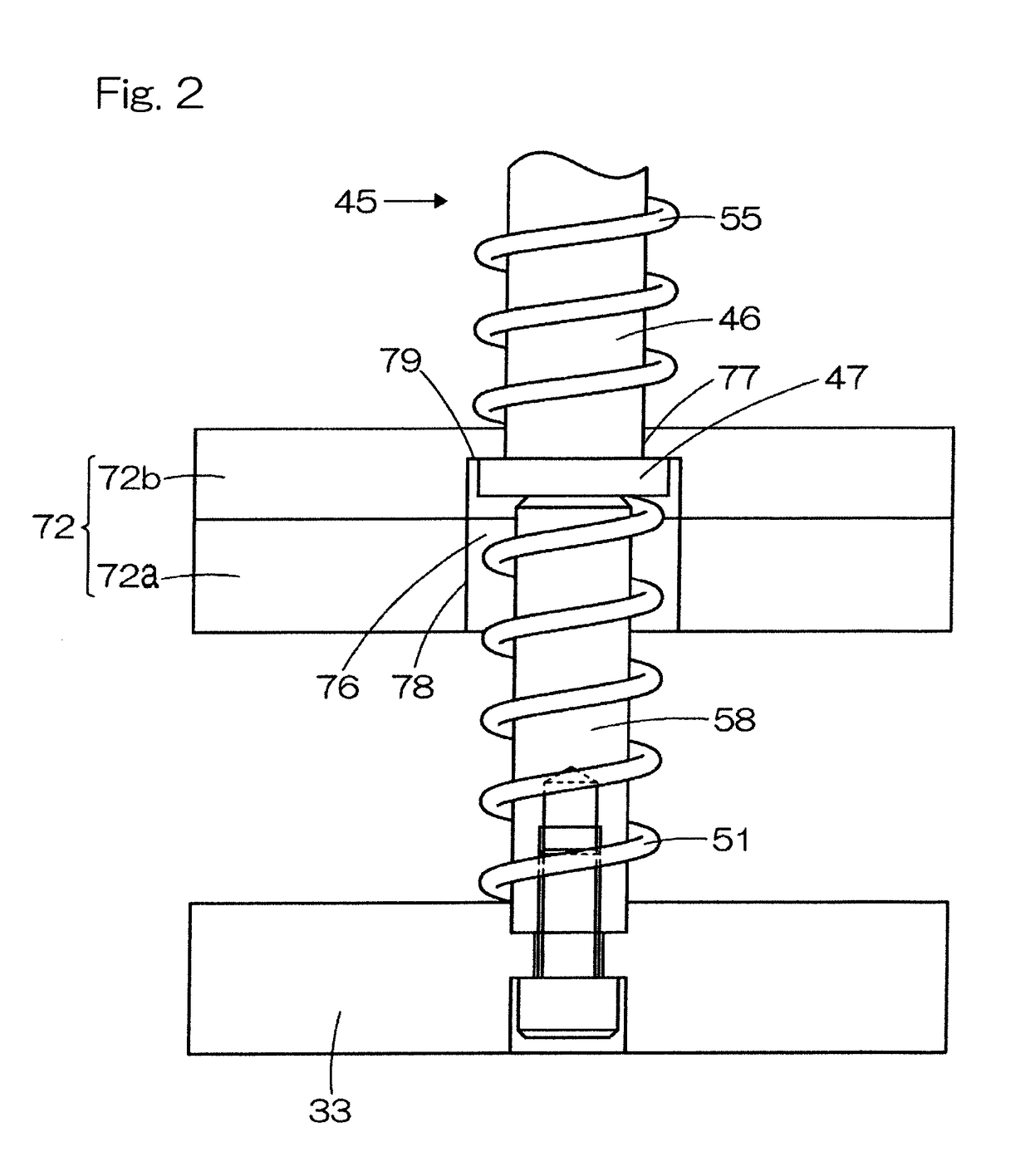
[0049]FIG. 1 is a cross-sectional view of a main part of an injection molding die 1 according to a first embodiment of the present invention. FIG. 2 is a diagram for describing a configuration around a stopper 58 of the injection molding die 1. FIG. 3 is a modification of the injection molding die 1 of the first embodiment. FIG. 4 is a cross-sectional view of a main part showing a state of the injection molding die 1 which is opened. FIGS. 5 to 7 are each a cross-sectional view of a main part showing a state of the injection molding die 1 during projection of a molded article. FIG. 8 is a schematic diagram showing a state where a molding piece 36 of the injection molding die 1 is trapped by another member in the middle of projection. FIGS. 9A and 9B are each a diagram for describing reaction forces of a lower spring 51 and an upper spring 55 used in a second projection mechanism 41 of the injection molding die 1. In the present embodiment, “up” and “upward direction” mean “up” and “...
PUM
| Property | Measurement | Unit |
|---|---|---|
| Force | aaaaa | aaaaa |
Abstract
Description
Claims
Application Information