Connector

Active Publication Date: 2016-09-15
YAZAKI CORP
View PDF13 Cites 8 Cited by
  • Summary
  • Abstract
  • Description
  • Claims
  • Application Information

AI Technical Summary

Benefits of technology

[0014]According to this, since the connector terminal is moved toward the apparatus-terminal together with the housing by the movable member via the motion direction converting mechanism, it is possible to electrically connect the connector terminal and the apparatus-terminal to each other by bringing the contact portion into press-contact with the apparatus-terminal. Therefore, for example, even when some or all of the plurality of terminals are connected to each other, it is not necessary to add an additional connecting member for each connection unit in addition to the connector terminal and the apparatus-terminal. Therefore, the structure for connecting the terminals to each other does not become complicated, and it is possible to connect the plurality of terminals to each other integrally. In addition, for example, it is not necessary to temporarily insert (temporary contact to the contact portion) the apparatus-terminal into the connector terminal, and even when connecting the plurality of terminals to each other, there is not a case where the effort to perform the corresponding temporary insertion work or the temporary contact work increases to the same extent to which the number of terminals increases, and the work becomes complicated. Furthermore, it is not necessary to additionally change the connector structure of the connection counterpart apparatus. For example, it is not necessary to provide the cam groove in one of the connector and the connection counterpart apparatus, and the cam follower (projection) in the other one of the connector and the connection counterpart apparatus, and it is also not necessary to position the cam groove and the cam follower between the connector and the connection counterpart apparatus.
[0015]In this case, as an example of the motion direction converting mechanism, the housing and the movable member respectively have the inclination portions which are inclined rearward with respect to the moving direction of the housing and are in slidable contact with each other, and the linear groove can be formed to extend along the inclination of the inclination portion. Accordingly since it is possible to relatively move the projection along the linear groove while the inclination portions of the housing and the movable member are slidable to each other, at this time, it is possible to stabilize the posture of the housing and the movable member.
[0016]In addition, the connector includes an exterior member which surrounds the housing and is fixed to the connection counterpart apparatus, and a slit which linearly extends along the moving direction of the housing in one of the housing and the exterior member, and a boss whi

Problems solved by technology

Therefore, when connecting the plural groups of bus bar terminals, the work becomes complicated since all of the bolt holes of the bus bar terminals of a connection target should communicate with each othe

Method used


Image

  • Connector
  • Connector
  • Connector

Examples


Example

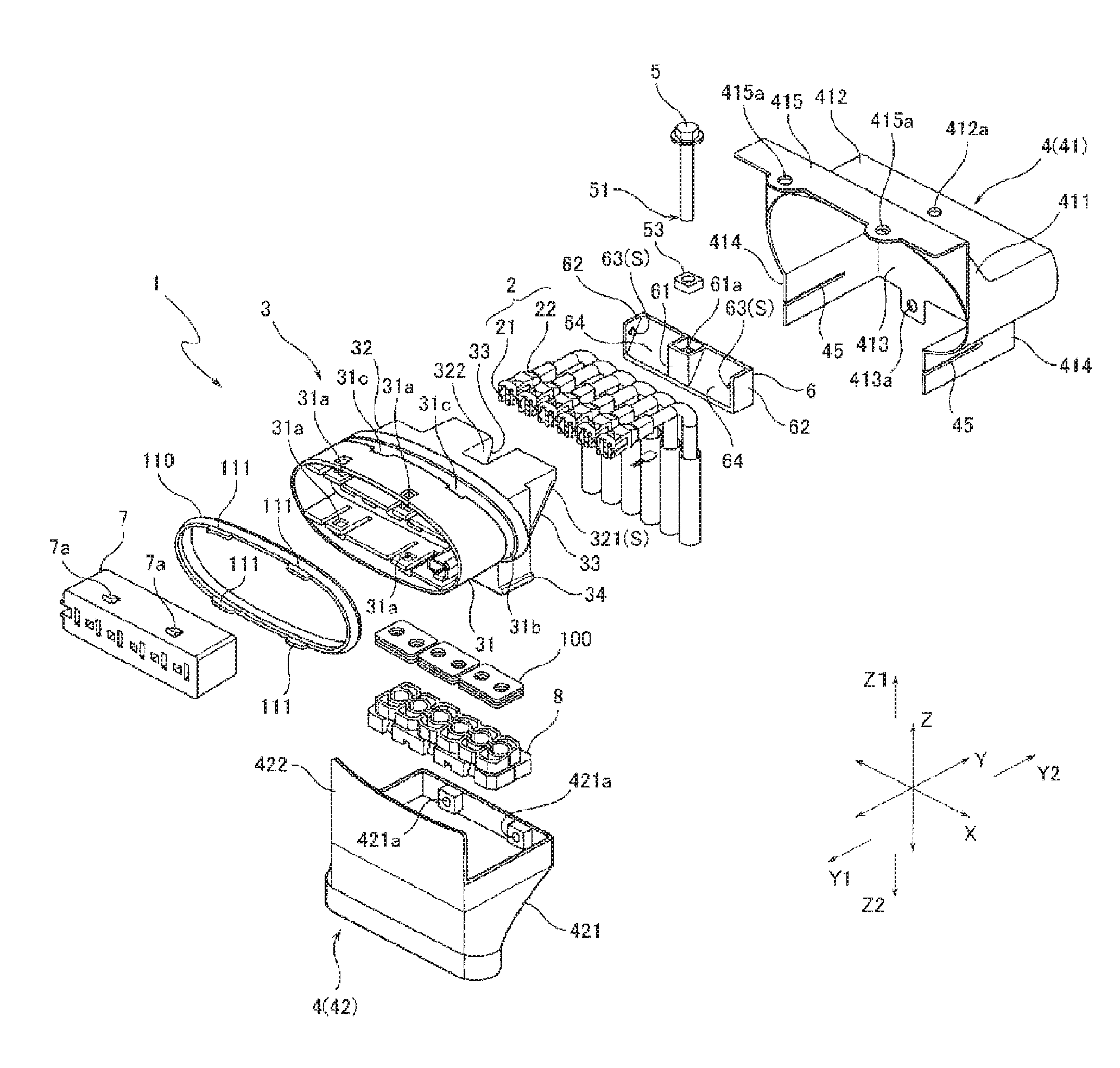
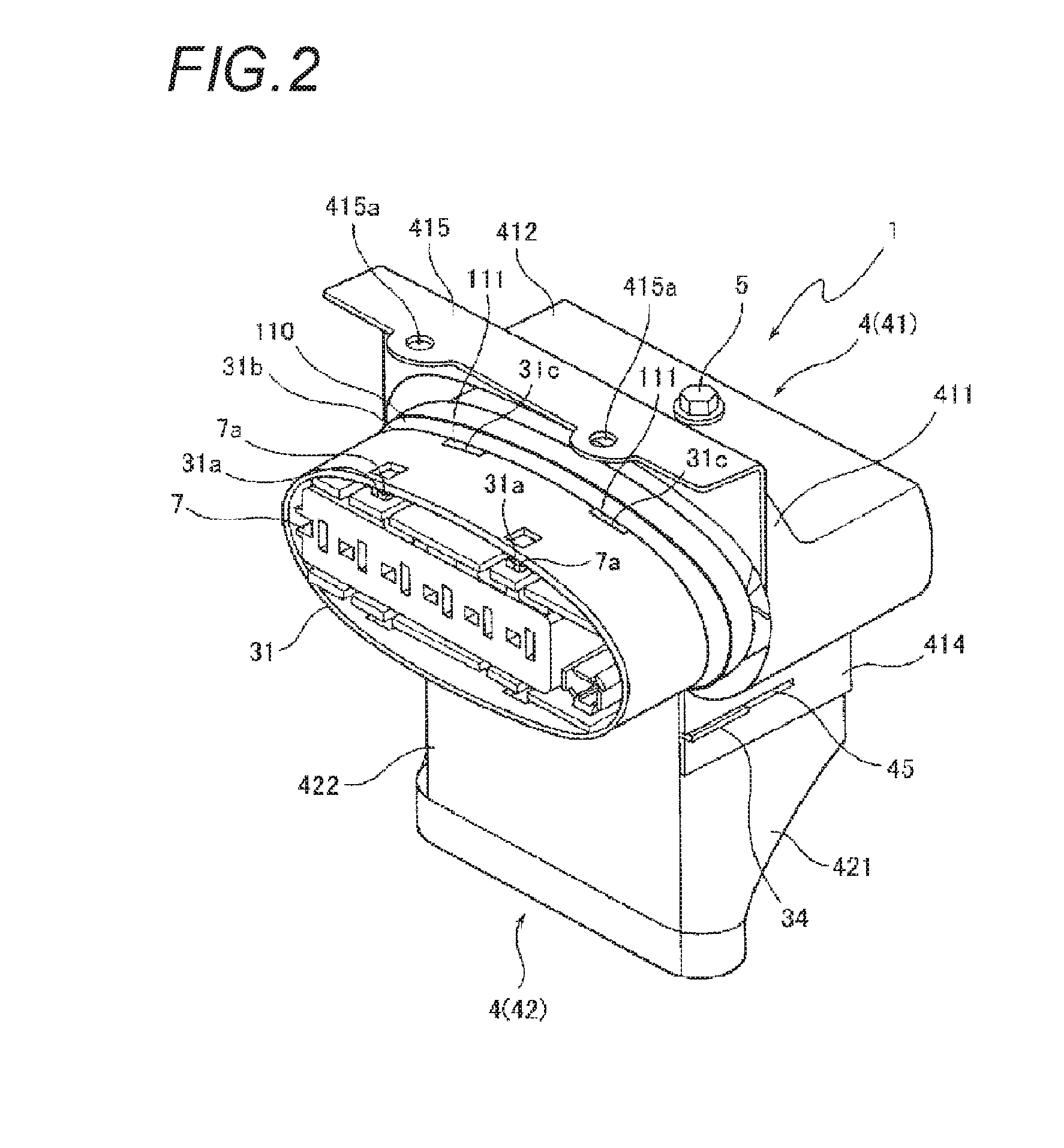
[0025]Hereinafter, a connector of the present invention will be described with reference to the accompanying drawings. FIGS. 1 and 2 illustrate a configuration of the entire connector according to an embodiment of the present invention. FIG. 1 is a perspective view illustrating a connector, in which the connector is disassembled into constituent members. FIG. 2 is a perspective view of the entire connector illustrating a state where the constituent members illustrated in FIG. 1 are assembled. In the following description, an arrow X direction illustrated in FIG. 1 is a horizontal direction, an arrow Y direction is a lateral direction, and an arrow Z direction is a vertical direction. In addition, regarding the lateral direction, an arrow Y1 direction in FIG. 1 is specified as a front side (forward), and an arrow Y2 direction is specified as a rear side (rearward). Regarding the vertical direction, an arrow Z1 direction in FIG. 1 is specified as an upper side (upward), and an arrow Z...


PUM


Abstract

A connector includes connector terminals having an elastically deformable contact portion which contacts an apparatus-terminal of a connection counterpart apparatus, a housing to which the connector terminals are assembled, a rotating member which is rotatable with respect to the housing by an external manipulation, and a movable member which moves the housing toward the connection counterpart apparatus via a motion direction converting mechanism which converts a rotation motion of the rotating member into a linear motion. The motion direction converting mechanism includes at least one projection in one of the housing and the movable member and at least one linear groove which meshes with the projection in the other one of the housing and the movable member, wherein the projection and the linear groove are inclined with respect to a moving direction of the housing.

Description

CROSS REFERENCE TO RELATED APPLICATIONS[0001]This application is a continuation of international patent application No. PCT / JP2014 / 084709 filed Dec. 26, 2014 based on Japanese Patent Application No. 2013-270510 filed Dec. 26, 2013; the contents of which are incorporated herein by reference in its entirety.BACKGROUND OF THE INVENTION[0002]1. Field of the Invention[0003]The present invention relates to a connector for electrically connecting a plurality of terminals to each other, and particularly to a connector which can reduce an insertion load when fitting respective apparatus-terminals to the plurality of connector terminals.[0004]2. Description of the Related Art[0005]As a connector structure for electrically connecting terminals to each other, for example, a structure in which two bus bar terminals having bolt holes are superposed to communicate with each of the bolt holes, and the bus bar terminals are fastened and fixed by bolts which communicate with the corresponding bolt ho...

Claims


Application Information

Patent Timeline
IPC IPC(8): H01R13/631H01R13/74H01R13/6581
CPCH01R13/631H01R13/748H01R13/6581H01R13/6315H01R13/6591H01R2107/00
Inventor KATO, HAJIMEGOTO, TATSUYAIMAI, HIROAKI
Owner YAZAKI CORP
Why Eureka
Try Eureka