Fan structure with non-circular circumference

a fan structure and non-circular technology, applied in the direction of non-positive displacement fluid engines, axial flow pumps, pump components, etc., can solve the problems of high heat generation, serious dipole noise generation of parallel fan structures, and inability to produce vibration, etc., to achieve the effect of reducing noise generation, reducing dipole noise generation, and saving costs

Active Publication Date: 2018-06-07
ASIA VITAL COMPONENTS SHENZHEN CO LTD
View PDF0 Cites 0 Cited by
  • Summary
  • Abstract
  • Description
  • Claims
  • Application Information

AI Technical Summary

Benefits of technology

[0010]When the fan structure of the present invention operates, the first hub is first driven to rotate. The rotation of the first hub will bring the transmission belt member to rotate counterclockwise or clockwise. Meanwhile, the second hub is also brought by the transmission belt member to rotate along with the first hub. At this point, due to a pressure difference between upper and lower surfaces of the blades on the transmission belt member, air at an air inlet of the frame is sucked into the receiving space in the frame and then flows out of the frame via an air outlet. By causing the transmission belt member to rotate continuously along a noncircular circumferential path to enable the operation of the fan structure, it is able to overcome the problem of serious resonance between fan frames of the conventional parallel fan structure caused by the mutually influenced vibration base-frequency of the parallelly connected fans. Moreover, since the transmission belt member of the fan structure according to the present invention operates along a non-circular circumferential path, it is able to suppress dipole noise generation and accordingly minimize the noise produced due to dipole-dipole interaction. In addition, with the present invention, it is able to save the costs for some parts, such as one stator unit and one magnetic element, which are considered necessary in the conventional parallel fan structure.
[0011]Therefore, the fan structure of the present invention can be manufactured at largely reduced material and production costs.

Problems solved by technology

Electronic products, such as computers and notebook computers, have internal elements that tend to produce a high amount of heat during operation thereof.
When a fan operates, the motor thereof will inevitably produce vibration as a result of the torque of the motor.
In addition, the parallel fan structure 1 is subjected to serious dipole noise generation due to dipole-dipole interaction between fans arranged in pairs.
Accordingly, the conventional parallel fan structure has the following disadvantages: (1) the fans thereof produce increased vibration when they operate; and (2) it produces serious noise due to dipole-dipole interaction.

Method used


Image

  • Fan structure with non-circular circumference
  • Fan structure with non-circular circumference
  • Fan structure with non-circular circumference

Examples


Embodiment Construction

[0019]The present invention will now be described with some preferred embodiments thereof and by referring to the accompanying drawings. For the purpose of easy to understand, elements that are the same in the preferred embodiments are denoted by the same reference numerals.

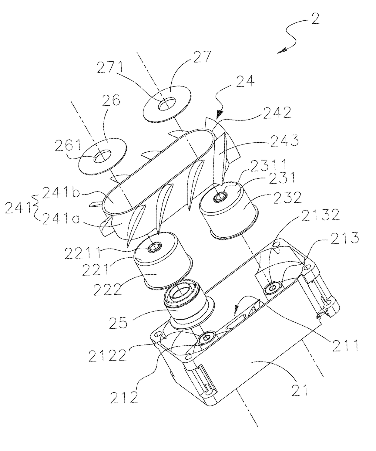
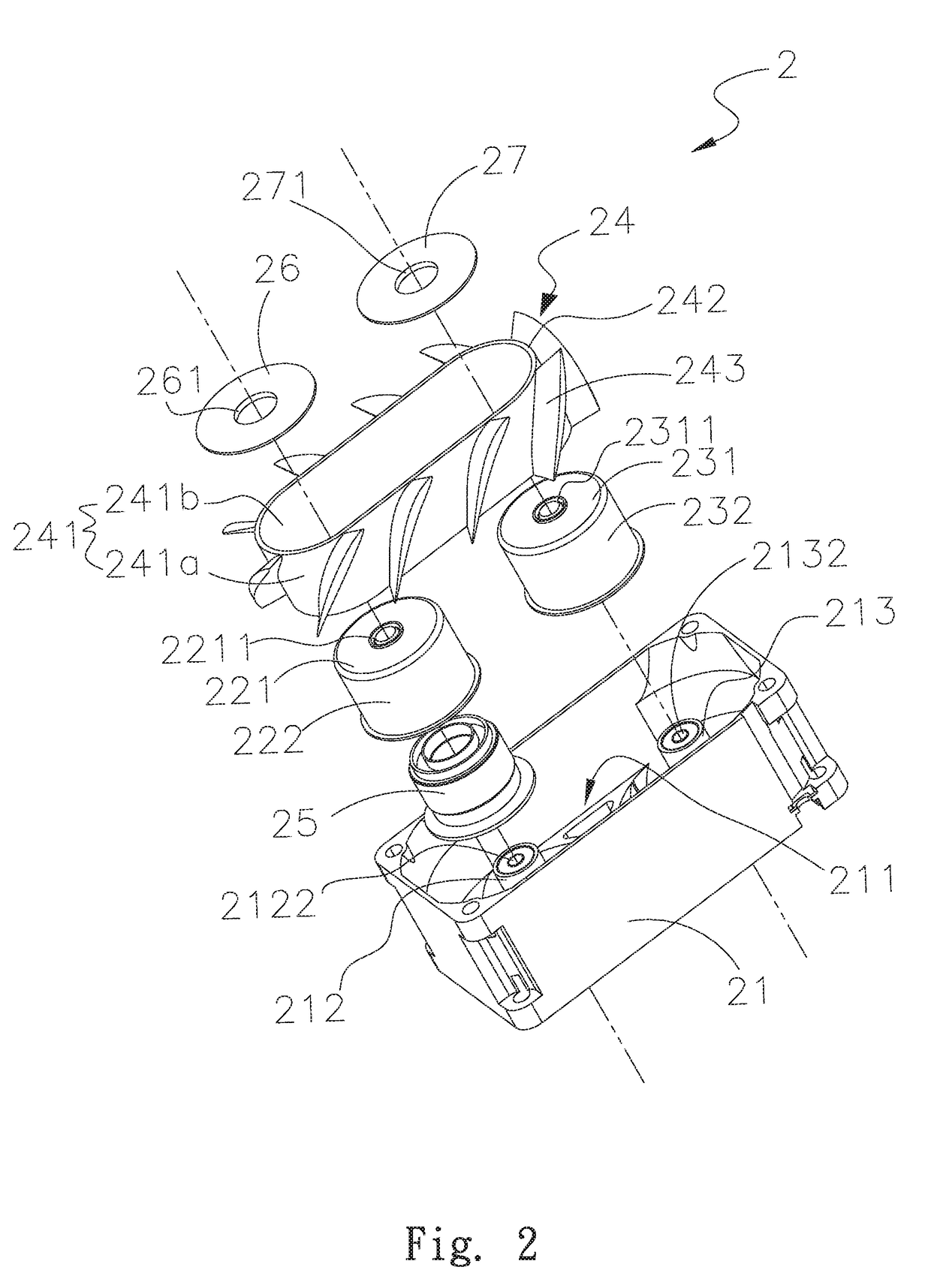
[0020]Please refer to FIG. 2, which is an exploded perspective view of a fan structure with non-circular circumference according to a first embodiment of the present invention, and to FIGS. 3 to 5, which are cutaway view, assembled sectional view and assembled bottom view, respectively, of the fan structure with non-circular circumference according to the first embodiment of the present invention. For the purpose of conciseness and clarity, the present invention is also briefly referred to as the fan structure and generally denoted by reference number 2 herein. As shown, the fan structure 2 according to the first embodiment includes a frame 21, a first hub 22, a second hub 23, a transmission belt member 24, a fir...


PUM


Abstract

A fan structure with non-circular circumference includes a frame, a first hub, a second hub, a transmission belt member, a first assembling member and a second assembling member. A first and a second base are provided in and protruded from a bottom of the frame. The first and the second hub are respectively mounted on the first and the second base, and a stator unit is provided between the first hub and the first base. The transmission belt member is fitted around side walls of the first and second hubs, and has a plurality of blades spaced on an outer surface thereof. The first and the second assembling member are correspondingly assembled to the tops of the first and the second hub. With the above arrangements, the fan structure can operate with largely reduced vibration and noise and can be manufactured at reduced material and production costs.

Description

FIELD OF THE INVENTION[0001]The present invention relates to a fan structure with non-circular circumference, and more particularly, to a fan structure with non-circular circumference that can operate with largely reduced vibration and noise and can be manufactured at reduced material and production costs.BACKGROUND OF THE INVENTION[0002]With the constant progress of scientific technology, people's reliance on various kinds of electronic apparatuses also increases. Electronic products, such as computers and notebook computers, have internal elements that tend to produce a high amount of heat during operation thereof. The produced heat must be timely removed from the electronic products to avoid the problem of overheating. Therefore, most electronic products are internally equipped with a fan, so that the electronic products in operation can always maintain at a temperature within the working temperature range set for them.[0003]FIG. 1 shows a conventional parallel fan structure 1 th...

Claims


Application Information

Patent Timeline
Patent Type & Authority Applications(United States)
IPC IPC(8): F04D29/38F04D19/00F04D29/32F04D29/52
CPCF04D29/384F04D29/522F04D29/329F04D19/002F04D19/00F04D33/00
Inventor CHANG, BOR-HAWCHEN, YU-TZUWANG, CHUNG-SHU
Owner ASIA VITAL COMPONENTS SHENZHEN CO LTD
Why Eureka
Try Eureka