Golf ball aerodynamic configuration

a technology of aerodynamic configuration and golf ball, which is applied in the field of golf balls, can solve the problems of increasing the distance of golf balls, increasing the cost of manufacturers, and immense time and financial commitment, and achieves the effects of maximizing the dimple coverage, interdigitation, and enlarging or reducing the size of dimples

Active Publication Date: 2018-06-14
ACUSHNET CO
View PDF6 Cites 3 Cited by
  • Summary
  • Abstract
  • Description
  • Claims
  • Application Information

AI Technical Summary

Benefits of technology

[0014]The present invention concerns golf balls with improved modified aerodynamic configurations and a method for improving dimple coverage, interdigitation, and non-alignment in golf ball dimple patterns by rotating repeating area elements about pre-determined center points, with further optional steps of expanding or contracting the elemental arrangements about pre-determined center points, enlarging or reducing the sizes of dimples, and adding extra dimples to occupy land areas created by the previous steps. In one embodiment, a golf ball comprises a core and a cover having a modified aerodynamic configuration having a base aerodynamic configuration with one or more repeating geometric elements each of which comprise one or more dimples, and wherein the elements of the base aerodynamic configuration have been rotated one or more degrees about a pre-determined center point of the element resulting in the modified aerodynamic configuration.
[0015]Preferably, the base aerodynamic configuration is selected from the group consisting of icosahedron, octahedron, cube, cuboctahedron, dodecahedron, icosidodecahedron, tetrahedron and dipyramid base geometry. In another embodiment, the elements may be rotated between about 3 and about 30 degrees. The elements may be rotated causing the dimples to shift ½, 1½, 2½ or 3½ dimple diameters relative to each other. In another embodiment, the elements may be either expanded or contracted after rotation. The base aerodynamic configuration may be maximized for dimple coverage. The elements may be expanded or contacted by an arrangement factor of about 0.920 to about 1.035 and the diameters of the dimples may be enlarged or reduced by a diameter factor of about 0.910 to about 1.030. In a preferred embodiment, a plurality of additional dimples is provided in blank spaces of land areas created by the rotation of the elements. More preferably, about 5 to about 90 dimples are added to the blank spaces. In another embodiment, the dimple coverage of the modified aerodynamic configuration may be increased by at least 1 percent from the base aerodynamic configuration, preferably by about 1 to about 15 percent from the base aerodynamic configuration, and more preferably from about 3 to about 13 percent from the base aerodynamic configuration.
[0016]A method of making a golf ball is disclosed, the golf ball having a core and a cover and a modified aerodynamic configuration, the method comprising the steps of: selecting one or more repeating geometric elements in a base aerodynamic configuration, each element of which comprises one or more dimples; and rotating the elements one or more degrees about a pre-determined center point of that element.

Problems solved by technology

However, in the late nineteenth century, players observed that, as golf balls became scuffed or marred from play, the balls achieved more distance.
These improvements have come at great cost to manufacturers.
For example, to determine if a particular ball design has desirable flight characteristics for a broad range of players, i.e., high and low swing speed players, manufacturers perform the mechanical golfer test with different ball launch conditions, which involves immense time and financial commitments.
Furthermore, it is difficult to identify incremental performance improvements using these methods due to the statistical noise generated by environmental conditions, which necessitates large sample sizes for sufficient confidence intervals.
It results from a difference in pressure that is created by a distortion in the air flow that results from the back spin of the ball.
The difference between the high pressure in front of the ball and the low pressure behind the ball reduces the ball speed and acts as the primary source of drag for a golf ball.
Dimple coverage gained by filling spaces with tiny dimples is not very effective, since tiny dimples are not good turbulence generators.
One disadvantage of these shapes is that they can sharply intrude into the surface of the ball, which may cause the drag to become excessive.
As a result, the ball may not make best use of momentum initially imparted thereto, resulting in an insufficient carry of the ball.
It has now been discovered, however, contrary to the disclosures of these patents, that reduced high-speed drag and increased low speed lift does not necessarily result in improved flight performance.
For example, excessive high-speed lift or excessive low-speed drag may result in undesirable flight performance characteristics.
The prior art is silent, however, as to aerodynamic features that influence other aspects of golf ball flight, such as flight consistency, as well as enhanced aerodynamic coefficients for balls of varying size and weight.

Method used


Image

  • Golf ball aerodynamic configuration
  • Golf ball aerodynamic configuration
  • Golf ball aerodynamic configuration

Examples


Embodiment Construction

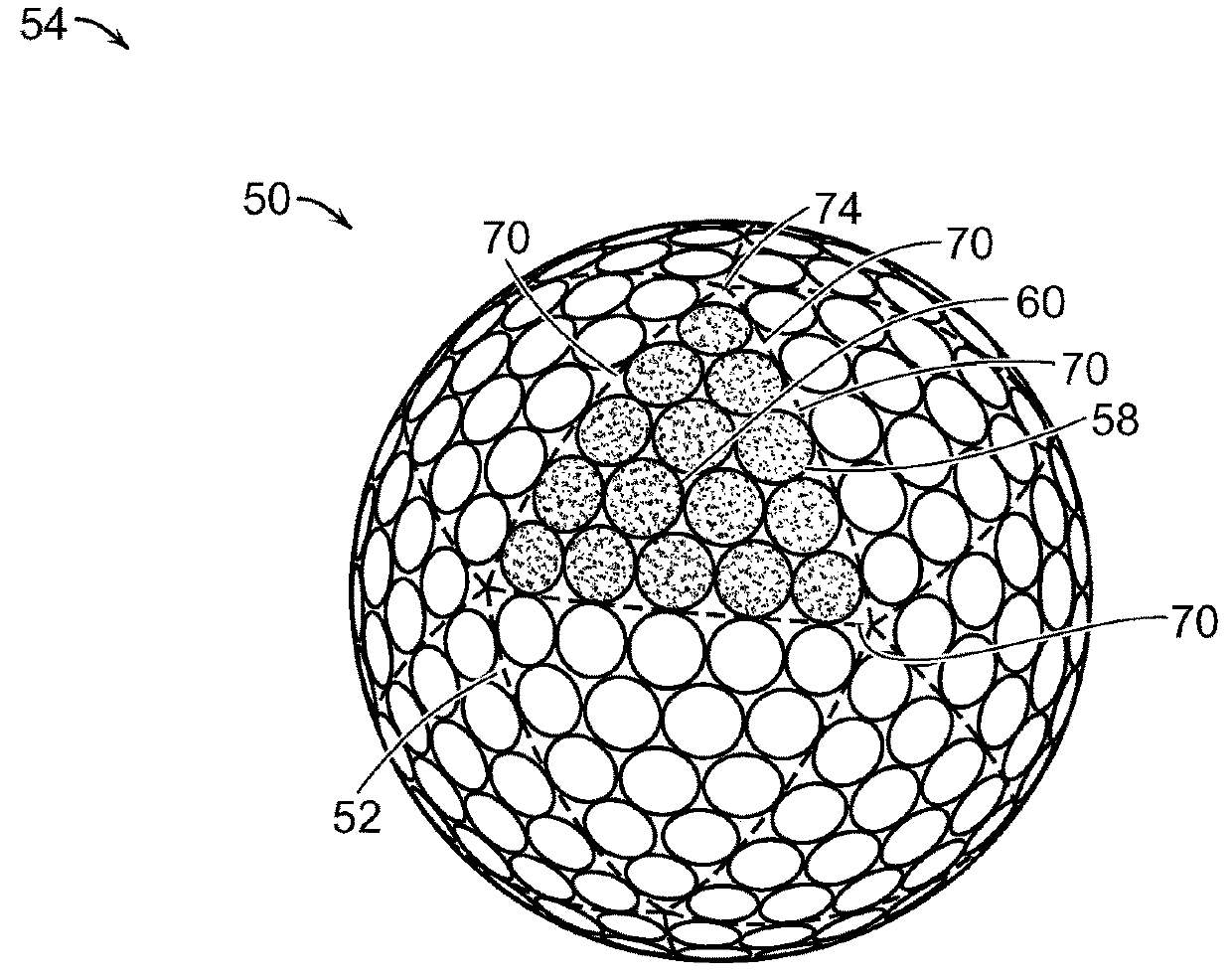
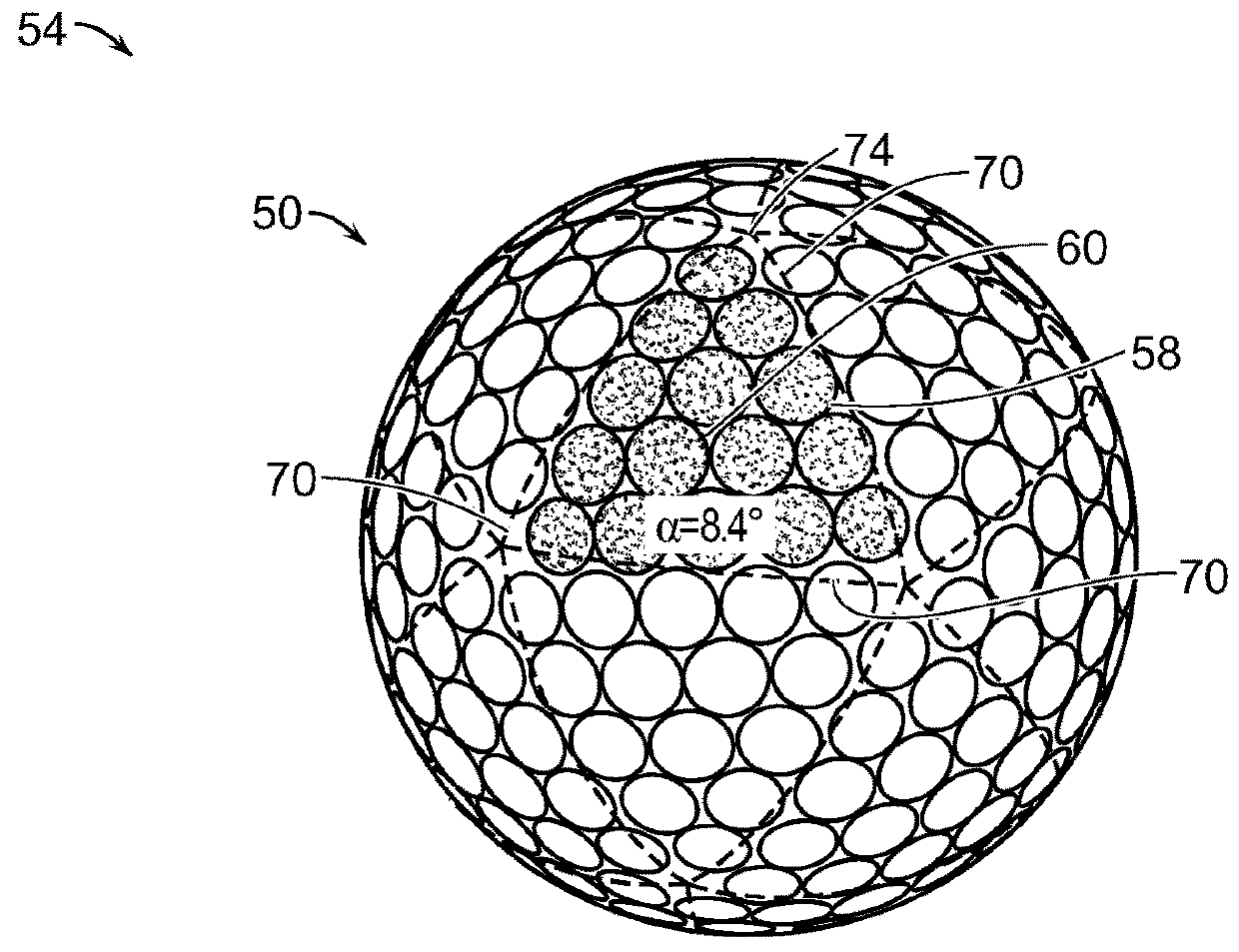
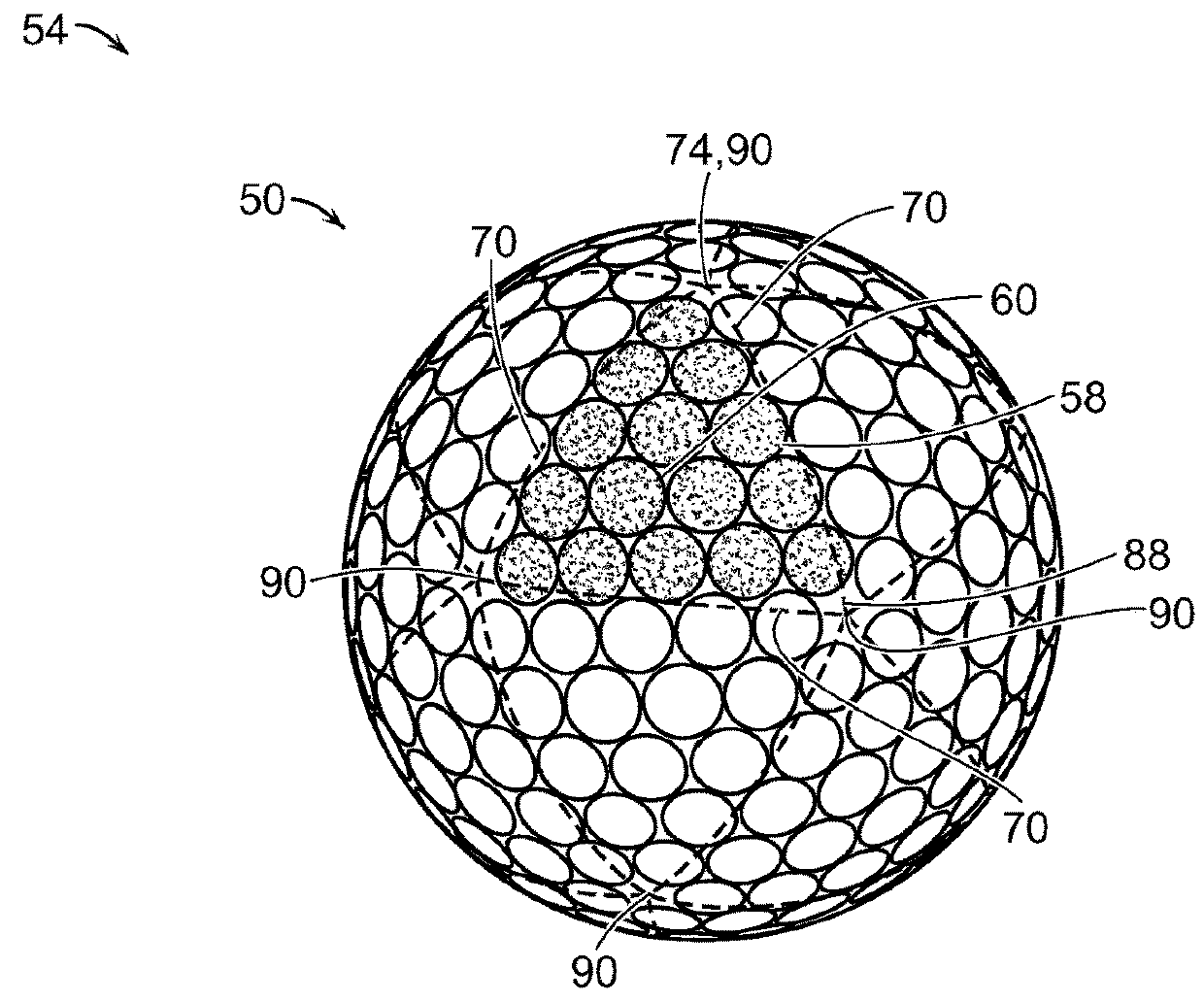
[0047]Dimple patterns 50 are typically generated by dividing a surface 52 of a ball 54 into repeating area elements of one or more types, and then filling like area elements with like arrangements of dimples 58. The invention adds the additional step of rotating the area element arrangements about pre-determined center points 60, with further optional steps of expanding or contracting the area element arrangements about pre-determined center points 60, enlarging or reducing the sizes of dimples, and adding extra dimples 62 to occupy land areas 64 created by the previous steps. It will be appreciated that the steps of rotating the area element arrangements and expanding or contracting the area element arrangements may be performed about any pre-determined points, but preferably are performed about a pre-determined centroid. It will also be appreciated that the steps of rotating the area element arrangements and expanding or contracting the area element arrangements may be performed a...


PUM


Abstract

The present invention concerns golf balls having a modified aerodynamic configuration and a method for creating a modified aerodynamic configuration that improves dimple coverage, interdigitation, and non-alignment in golf ball dimple patterns by rotating the repeating area elements about pre-determined center points, with further optional steps of expanding or contracting the elemental arrangements about pre-determined center points, enlarging or reducing the sizes of dimples, and adding extra dimples to occupy land areas created by the previous steps. The resulting modified aerodynamic configuration with a rotated element has increased dimple coverage, greater interdigitation and improved non-alignment.

Description

FIELD OF THE INVENTION[0001]The present invention relates to golf balls, and more particularly, to golf balls that have rotation of repeating elements in their dimple patterns resulting in improved coverage, inter-digitation and non-alignment.BACKGROUND OF THE INVENTION[0002]The flight of a golf ball is determined by many factors. The majority of the properties that determine flight are outside of the control of the golfer. While a golfer can control the speed, the launch angle, and the spin rate of a golf ball by hitting the ball with a particular club, the final resting point of the ball depends upon golf ball aerodynamics, construction and materials, as well as environmental conditions, e.g., terrain and weather. Since flight distance and consistency are critical factors in reducing golf scores, manufacturers continually strive to make even the slightest incremental improvements in golf ball flight consistency and flight distance, e.g., one or more yards, through various aerodyna...

Claims


Application Information

Patent Timeline
Patent Type & Authority Applications(United States)
IPC IPC(8): A63B37/00
CPCA63B37/0006A63B37/0021A63B37/0074A63B37/002A63B37/00065
Inventor AOYAMA, STEVEN
Owner ACUSHNET CO
Why Eureka
Try Eureka