Digital-drive pulse-width-modulated output system

a pulse width modulation and output system technology, applied in the field of display systems, can solve the problems of limited to relatively small displays and inapplicability of digital storage for conventional flat-panel displays, and achieve the effects of flexible, scalable, and efficient digital display systems

Active Publication Date: 2018-07-12
X DISPLAY CO TECH LTD
View PDF59 Cites 65 Cited by
  • Summary
  • Abstract
  • Description
  • Claims
  • Application Information

AI Technical Summary

Benefits of technology

[0057]The present invention provides a highly integrated active-matrix micro-LED display with small micro-controllers associated with each pixel. By providing external load, dig...

Problems solved by technology

However, conventional schemes for providing temporal control, for example pulse width modulation, are generally employed in passive-matrix displays which suffer from flicker and are therefore limited to relatively small display...

Method used


Image

  • Digital-drive pulse-width-modulated output system
  • Digital-drive pulse-width-modulated output system
  • Digital-drive pulse-width-modulated output system

Examples


Embodiment Construction

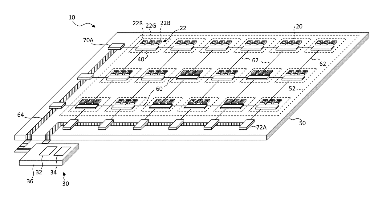
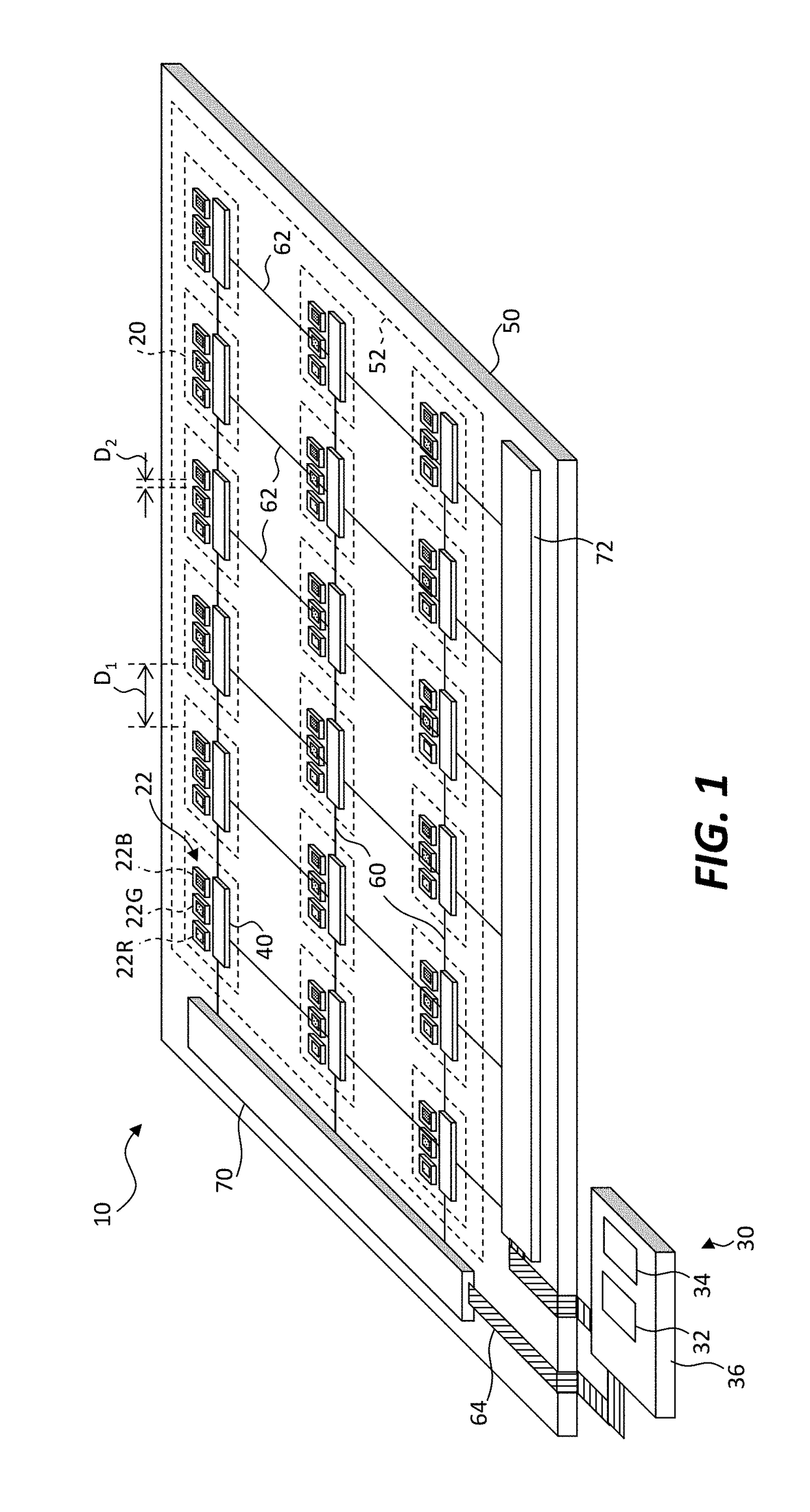
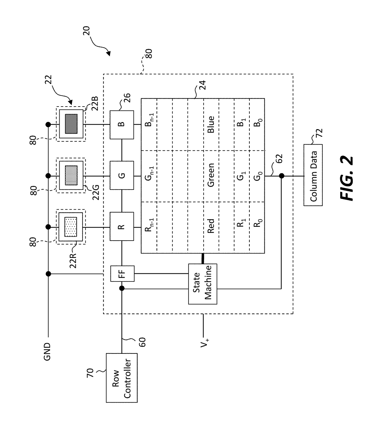
[0070]Embodiments of the present invention provide a scalable active-matrix digital display having efficient constant-current output suitable for inorganic light-emitting diodes. Referring to the perspective illustration of FIG. 1 and the corresponding detailed schematic of FIG. 2, a digital-drive display system 10 includes an array of pixels 20 arranged in rows and columns on a display substrate 50. Each pixel 20 has an output device 22, a serial digital memory 24 responsive to a load timing signal for receiving and storing a multi-bit digital pixel value during an uninterrupted load time period, and a drive circuit 26 responsive to a pulse-width-modulation (PWM) timing signal and to the multi-bit digital pixel value stored in the serial digital memory 24 to drive the output device 22 during an uninterrupted output time period subsequent to the load time period. The serial digital memory 24 can be, for example, a multi-bit digital random-access memory (e.g., an SRAM or DRAM) contro...


PUM


Abstract

An active-matrix digital-drive display system includes an array of pixels. Each pixel has an output device, a serial digital memory responsive to a load timing signal for receiving and storing a multi-bit digital pixel value during an uninterrupted load time period, and a drive circuit responsive to a pulse-width-modulation (PWM) timing signal and to the multi-bit digital pixel value to drive the output device during an uninterrupted output time period. A controller external to the array of pixels provides to each pixel the load timing signal and the multi-bit digital pixel value during the load time period and the PWM timing signal during the output time period. The PWM timing signal has multiple different PWM time periods that are sequentially provided at different times to the pixels. Each PWM time period has a different temporal length corresponding to a bit of the multi-bit digital pixel value.

Description

PRIORITY APPLICATION[0001]This application claims priority to and benefit of U.S. Patent Application No. 62 / 444,753, filed Jan. 10, 2017, entitled Digital-Drive Pulse-Width-Modulated Output System, by Rotzoll et al., the content of which is incorporated by reference in its entirety.CROSS REFERENCE TO RELATED APPLICATIONS[0002]Reference is made to U.S. patent application Ser. No. 14 / 835,282 filed Aug. 25, 2015, entitled Bit-Plane Pulse Width Modulated Digital Display System, by Cok et al., U.S. patent application Ser. No. 15 / 005,869, filed Jan. 25, 2016, entitled Distributed Pulse Width Modulation Control, by Cok, and U.S. Provisional Patent Application No. 62 / 334,351, filed May 10, 2016, entitled Multi-Pixel Distributed Pulse Width Modulation Control, by Cok et al., the contents of which are incorporated by reference herein in their entirety.FIELD OF THE INVENTION[0003]The present invention relates to display systems using digital pixel values driven by pulse-width modulation.BACKGR...

Claims


Application Information

Patent Timeline
IPC IPC(8): G09G3/3233H01L25/16G09G3/3283G09G3/20
CPCG09G3/3233H01L25/167G09G3/3283G09G3/2003H01L27/1214G09G2360/12G09G2310/08G09G2310/0286G09G2320/0646G09G2320/0666G09G2300/0452H01L33/48G09G3/2007G09G3/2085G09G2300/0426G09G2300/0857G09G2320/064H01L25/0753
Inventor ROTZOLL, ROBERT R.COK, RONALD S.
Owner X DISPLAY CO TECH LTD
Why Eureka
Try Eureka