
Error control coding for single error correction and double error detection

a technology of error correction and error detection, applied in the field of data processing systems, can solve the problems of no capability for correcting hard bit errors, additional overhead associated, and one or more bit errors within the data block, and achieve low overhead implementation, good error correction/detection capabilities, and low latency or pipeline implementation

Active Publication Date: 2013-02-19
ARM LTD
View PDF6 Cites 18 Cited by
  • Summary
  • Abstract
  • Description
  • Claims
  • Application Information

AI Technical Summary

Benefits of technology

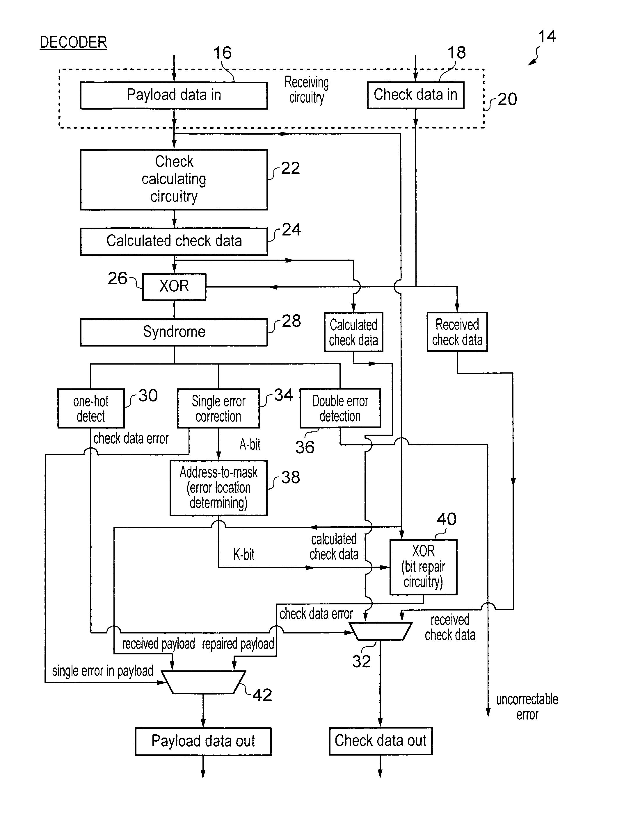
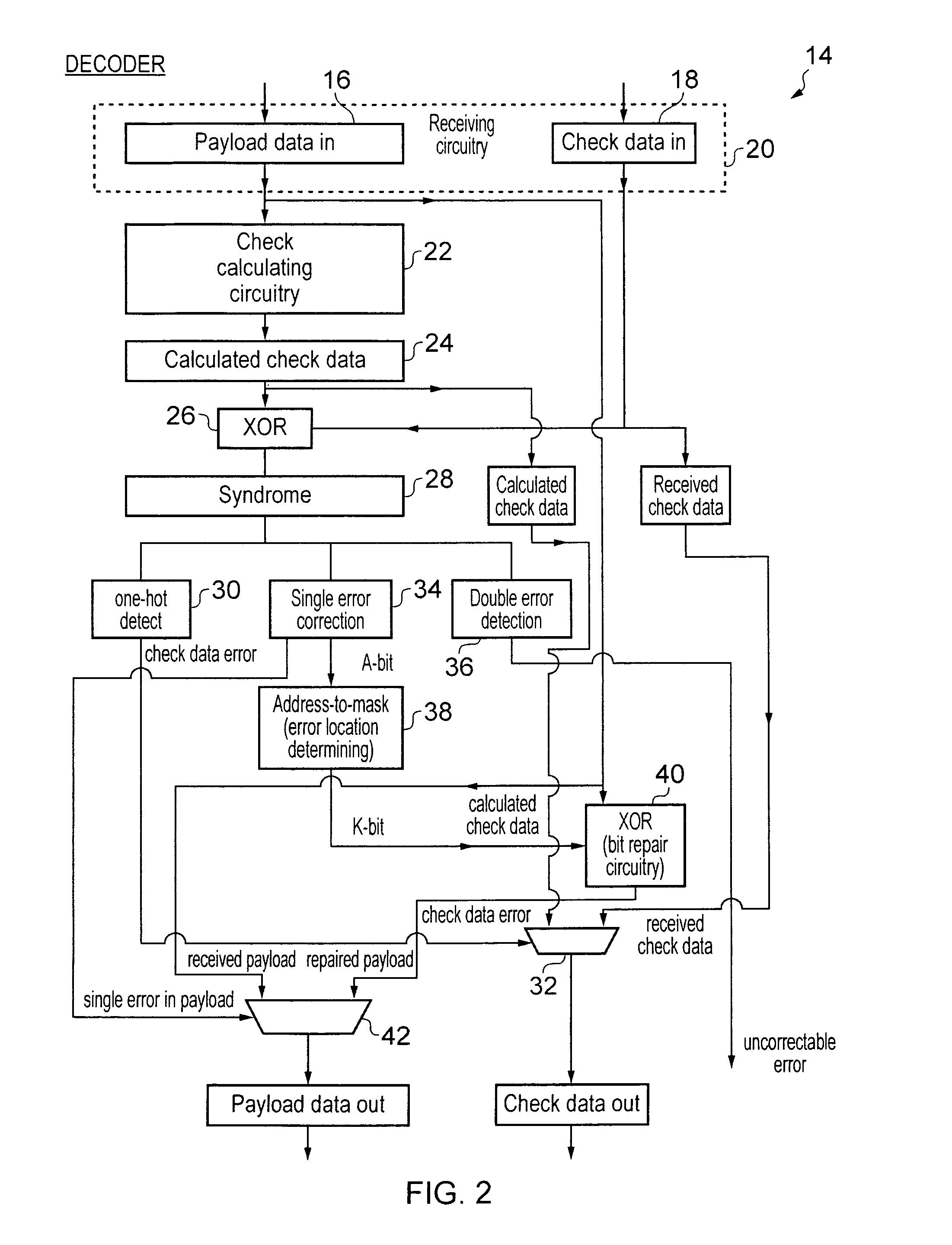
The present technique reduces the time and resources needed to identify the location of a specific data word that has a bit error in a computer system. This is achieved by using a check data structure that includes an address field that converts a set of addresses into a one-to-one mapping with the bit error. This approach also allows for a checksum to be used for signal error correction or single error correction and double error detection, while keeping the size of the check data low to minimize processing and storage overhead. The patent text also mentions the use of double error detection circuitry and bit repair circuitry in parallel to achieve efficient processing and low latency. The compact check data representation with good error correction and low overhead makes it useful in forming check data for storage and transmission.

Problems solved by technology

The blocks of data may be stored within a memory, transmitted across a data path or subject to some other action which can result in one or more bit errors within the block of data.
A simple parity bit may serve to detect a single bit error, but have no capability for correcting a hard bit error.
Although the action of error correction and error detection is desirable, there is an additional overhead associated with storing, writing, reading, transmitting etc the error control codes in association with the data block.
Furthermore, the processing required to use the error control codes to identify and / or detect the bit errors represents an overhead in terms of the circuitry required and / or additional latency which may be involved in accessing a block of data.

Method used


Image

  • Error control coding for single error correction and double error detection
  • Error control coding for single error correction and double error detection
  • Error control coding for single error correction and double error detection

Examples


Embodiment Construction

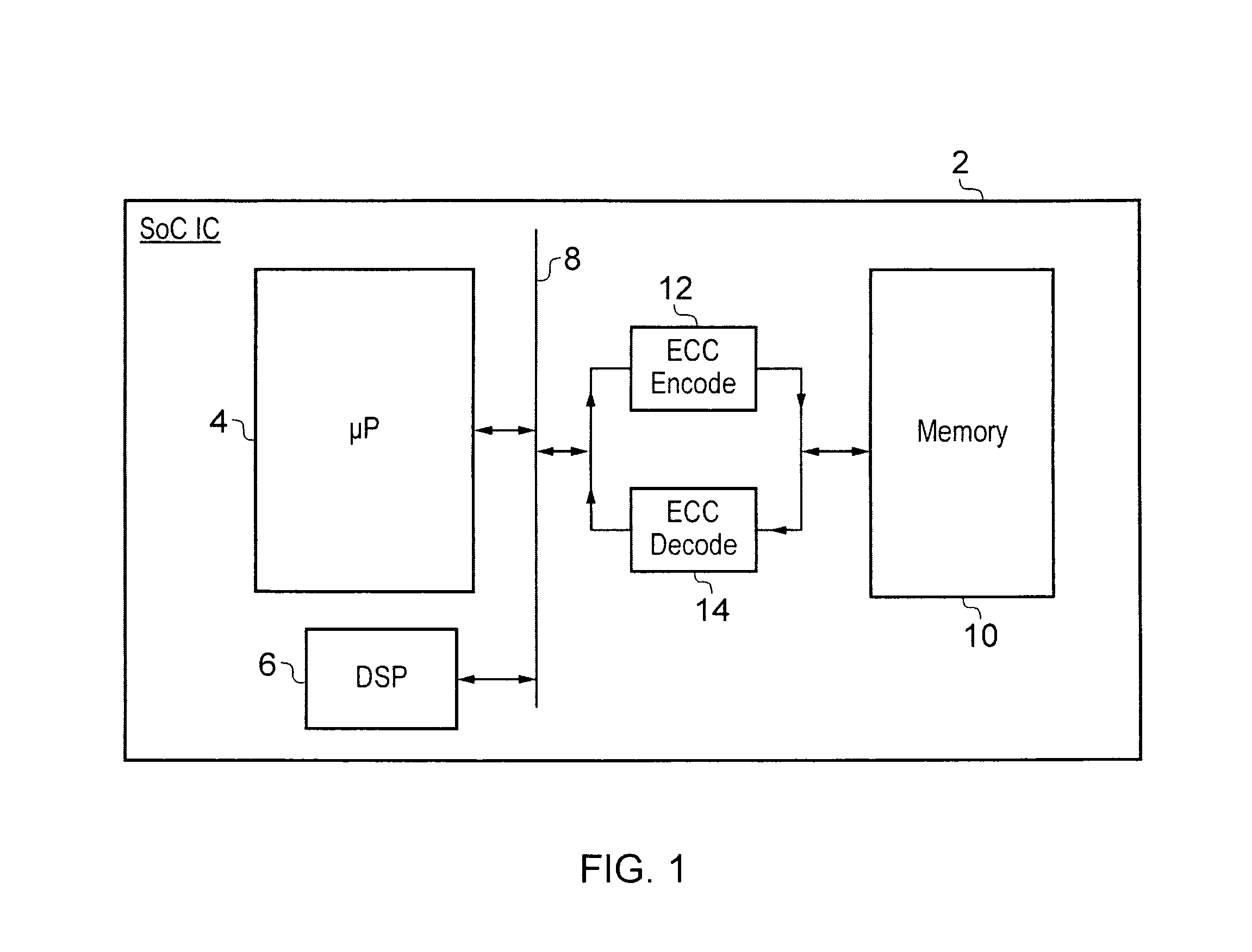
[0088]FIG. 1 schematically illustrates a system-on-chip integrated circuit 2 including a processor core 4 and a digital signal processor 6 connected via a system bus 8 to a memory 10. An Error Control Code (ECC) encoder 12 is disposed in the write path to the memory 10. An Error Control Code decoder 14 is disposed in the read path from the memory 10. It will be appreciated that in practice the ECC decoder 14 may contain circuitry that can also serve as the ECC encoder 12 and thus duplication of this hardware resource an be avoided. In FIG. 1 the ECC encoder 12 and the ECC decoder 14 are separately shown for the sake of simplicity.

[0089]When a block of payload data is written by the processor core 4 or the digital processor 6 to the memory 10, then it passes through the ECC encoder 12 where it is processed and check data added to the payload data. When a block of data is read from the memory 10, it passes through the ECC decoder 14 where the check data is recalculated and compared wi...


PUM


Abstract

An error correction coding is provided that generates P bits of check data from K M-bit words of payload data. The P bits of check data include an address field A, a bit error indicating field E and an auxiliary field P−(E+A). The address field encodes a set of error addresses which has a cardinality equal to the bit size K of the payload data and providing a one-to-one mapping between values of the address field and the locations of a single bit error within the payload data. The bit error indicating field indicates if a bit error is present. The auxiliary field is a minimum size bit vector such that together with the address field and the bit area indicating field it provides a checksum for a systematic code for the payload data with a minimum Hamming distance serving to provide either single error correction capability or single error correction and double error detection capability.

Description

BACKGROUND OF THE INVENTION[0001]1. Field of the Invention[0002]This invention relates to the field of data processing systems. More particularly, this invention relates to the field of error correcting and error detecting mechanisms within data processing systems.[0003]2. Description of the Prior Art[0004]It is known to provide Error Control Coding (ECC) for use in association with blocks of data. The blocks of data may be stored within a memory, transmitted across a data path or subject to some other action which can result in one or more bit errors within the block of data. The error correcting and / or error detecting codes associated with the block of data may provide a variety of different capabilities for correcting and / or detecting bit errors within the block of data. A simple parity bit may serve to detect a single bit error, but have no capability for correcting a hard bit error. More sophisticated error control codes may be capable of detecting and correcting one or more bi...

Claims


Application Information

Patent Timeline
Patent Type & Authority Patents(United States)
IPC IPC(8): G06F11/00
CPCG06F11/1048H03M13/03H03M13/033H03M13/13H03M13/136H03M13/19
Inventor WEZELENBURG, MARTINUS CORNELISCONWAY, THOMAS KELSHAW
Owner ARM LTD
Learn More