Low latency synchronous memory performance switching using update control

a technology of update control and synchronous memory, applied in memory systems, sustainable buildings, instruments, etc., can solve problems such as high power consumption, and achieve the effects of reducing the power consumed by synchronous memory devices, increasing performance, and high speed modes

Active Publication Date: 2011-11-08
NVIDIA CORP
View PDF4 Cites 17 Cited by
  • Summary
  • Abstract
  • Description
  • Claims
  • Application Information

AI Technical Summary

Benefits of technology

[0008]A system and method for configuring synchronous memory device to switch into and out of different speed modes without significantly disturbing the frequency of the clock input to the clock circuitry, e.g., PLL or DLL, allows for low speed modes to be used more frequently and for shorter periods of time in order to reduce the power consumed by the synchronous memory device. A system and method for configuring synchronous memory device to switch into and out of different speed modes also allows for higher speed modes to be used more frequently and for shorter periods of time in order to increase performance by increasing the available bandwidth to and from the synchronous memory device. In some embodiments of the present invention, clock circuitry within the synchronous memory device receives the full speed clock signal whether or not the synchronous memory

Problems solved by technology

Therefore, the low speed mode is sometimes no

Method used


Image

  • Low latency synchronous memory performance switching using update control
  • Low latency synchronous memory performance switching using update control
  • Low latency synchronous memory performance switching using update control

Examples


Embodiment Construction

[0025]In the following description, numerous specific details are set forth to provide a more thorough understanding of the present invention. However, it will be apparent to one of skill in the art that the present invention may be practiced without one or more of these specific details. In other instances, well-known features have not been described in order to avoid obscuring the present invention.

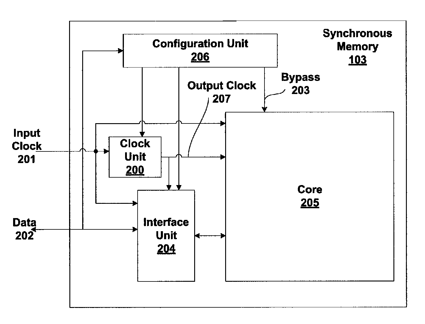
[0026]A synchronous memory device is configured to switch into and out of different speed modes depending on the memory bandwidth that is needed by a processing device that is coupled to the synchronous memory device. A variety of different data transaction rates may be specified by the different speed modes to provide several different performance levels. A DLL or PLL that produces an internal clock is locked to a full speed clock frequency and an output of the PLL or DLL remains substantially locked when a different speed (other than full speed) is used. Because the PLL or DLL does no...


PUM


Abstract

A synchronous memory device is configured to switch into and out of a full speed mode to change speed the speed of data transactions without significantly disturbing the frequency of a clock input to a PLL or DLL that provides the internal clock for the synchronous memory device. Since the PLL or DLL receives a clock signal whether or not the synchronous memory device is in a non-full speed mode, the PLL or DLL does not need to settle or relock when the clock signal is reapplied to exit a different speed mode and return to the full speed mode. Therefore, the latency incurred to switch into and out of different speed modes is reduced by eliminating or substantially reducing the time for settling or relocking the PLL or DLL.

Description

CROSS-REFERENCE TO RELATED APPLICATIONS[0001]This application claims benefit of U.S. provisional patent application Ser. No. 60 / 891,917, filed Feb. 27, 2007, which is herein incorporated by reference.BACKGROUND OF THE INVENTION[0002]1. Field of the Invention[0003]The present invention generally relates to synchronous memory devices and more specifically to reducing the latency needed to switch the speed of data transfers to and from the synchronous memory device.[0004]2. Description of the Related Art[0005]Conventional commercially available synchronous memory devices, such as DRAM (dynamic random access memory) or other clocked memory devices that use clocks or other signals to control the speed of their communication are at times configured to operate in a low speed mode in order to reduce the power consumed by a system including the synchronous memory device. The low speed mode is particularly useful as the number of portable, battery-powered devices has increased. In order to ch...

Claims


Application Information

Patent Timeline
IPC IPC(8): G06F12/00
CPCG11C7/1066G11C7/1093G11C7/222G06F1/324G06F1/3275Y02B60/1228Y02B60/1217Y02D10/00
Inventor SCHULZE, HANS WOLFGANGNEWCOMB, RUSSELL R.WAGNER, BARRY A.
Owner NVIDIA CORP
Why Eureka
Try Eureka