Pushbutton switch member

a technology of pushbutton switch and switch body, which is applied in the direction of electric switches, tactile feedback, electric apparatus, etc., can solve the problems of short stroke from the start of pushing until the metal dome deforms, the effect of weak click feeling, long stroke and favorable operation feeling

Active Publication Date: 2018-08-02
SHIN-ETSU POLYMER CO LTD
View PDF5 Cites 12 Cited by
  • Summary
  • Abstract
  • Description
  • Claims
  • Application Information

AI Technical Summary

Benefits of technology

[0023]The present invention provides a pushbutton switch member capable of achieving a favorable operation

Problems solved by technology

For example, when a positional difference occurs between a pushing position on the key and the central top part of the metal dome, a favorable click feeling cannot be obtained.
However, the conventionally known pushbutton switch member described above has the following problems.
The pushbutton switch member disclosed in JP 10-188728 has a problem that a positional difference is likely to occur between the metal dome and a rubber switch that is simply disposed above the metal dome.
The pushbutton switch member disclosed therein has another problem that a stroke from start of pushing until the metal dome deforms to turn on the switch is short.
In the pushbutton switc

Method used


Image

  • Pushbutton switch member
  • Pushbutton switch member
  • Pushbutton switch member

Examples


first embodiment

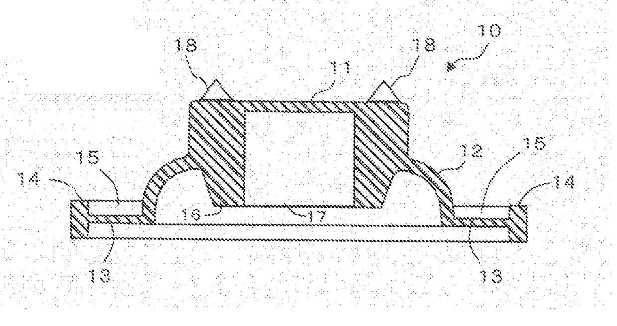
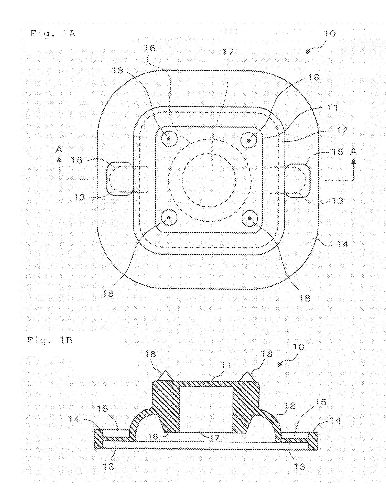
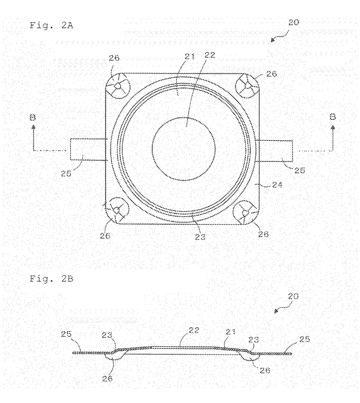
[0058]FIGS. 1A and 1B illustrate a transparent plan view (FIG. 1A) of an operation key included in a pushbutton switch member according to a first embodiment and a line A-A cross-sectional view (FIG. 1B) taken along line A-A in this transparent plan view. FIGS. 2A and 2B illustrate a plan view (FIG. 2A) of a dome-shaped movable contact included in the pushbutton switch member according to the first embodiment and a line B-B cross-sectional view (FIG. 2B) taken along line B-B in this plan view. FIG. 3 illustrates a transparent plan view when the pushbutton switch member according to the first embodiment in which the dome-shaped movable contact illustrated in FIGS. 2A and 2B is fixed below the operation key illustrated in FIGS. 1A and 1B is disposed on a circuit board, a line C-C cross-sectional view taken along line C-C in this transparent plan view, and a line D-D cross-sectional view taken along line D-D in this transparent plan view. FIG. 4 illustrates a back-surface perspective v...

second embodiment

[0080]The following describes a pushbutton switch member according to a second embodiment. In the second embodiment, any component identical to that in the first embodiment is denoted by an identical reference sign, and any duplicate description of configuration and operation thereof will be omitted but should be given by referring to the description in the first embodiment.

[0081]FIGS. 6A and 6B illustrate a transparent plan view (FIG. 6A) of the pushbutton switch member according to the second embodiment and a line E-E cross-sectional view (FIG. 6B) taken along line E-E (line bent at the center of the pushbutton switch member) in this transparent plan view. FIG. 7 illustrates a back-surface perspective view of the pushbutton switch member illustrated in FIGS. 6A and 6B when obliquely viewed from back.

[0082]The pushbutton switch member 80 according to the second embodiment includes a dome-shaped movable contact 70, and an operation key 60 disposed on a protrusion side of the movable...

third embodiment

[0093]The following describes a pushbutton switch member according to a third embodiment. In the third embodiment, any part common to that in the above-described embodiments is denoted by the same reference sign, and description of the configuration or operation thereof will be given by the corresponding description in the above-described embodiments, thereby omitting any duplicate description.

[0094]FIGS. 8A and 8B illustrate a transparent plan view (FIG. 8A) of the pushbutton switch member according to the third embodiment and a line C-C cross-sectional view (FIG. 8B) thereof taken along line C-C in this transparent plan view.

[0095]This pushbutton switch member 30a according to the present embodiment has a configuration same as that of the pushbutton switch member 30 according to the first embodiment except that a protrusion 18a provided on the top surface of the key body 11 has a shape different from those of the protrusions 18 of the pushbutton switch member 30 according to the f...


PUM


Abstract

A pushbutton switch includes: a dome-shaped movable contact; and an operation key on a side of the movable contact. Pushing the operation key causes the movable contact to electrically connect at least two contacts. The operation key includes: a key body; a dome connected with an exterior of the key body and deformable by pushing the key body; a foot connected with an exterior of the dome; and a protrusion on top of the key body, protruding from the top, and deformable by compression. The movable contact includes: an upper contact in contact with a site below the key body and contacting the at least two contacts when the key body is pushed; and an outer fixing part at the upper contact in a radial direction and fixed outside of the key body of the operation key in the radial direction.

Description

CROSS REFERENCE[0001]The present application claims the benefit of priorities of Japanese Patent Application No. 2015-146647, filed on Jul. 24, 2015 in Japan and Japanese Patent Application No. 2016-059707, filed on Mar. 24, 2016 in Japan, the entire contents of both JP 2015-146647 and JP 2016-059707 are incorporated herein by reference. The entire contents of patents, patent applications, and literatures cited in the present application are also incorporated herein by reference.TECHNICAL FIELD[0002]The present invention relates to a pushbutton switch member.RELATED ART[0003]In a conventionally known pushbutton switch member, a switch is turned on through deformation of a metal dome when pushing is externally applied on a central top part of the metal dome (see Japanese Patent Laid-open No. 10-188728, for example). Along with downsizing of keys and spaces therebetween due to recent downsizing of an instrument in which a pushbutton switch member is incorporated, it has been increasin...

Claims


Application Information

Patent Timeline
IPC IPC(8): H01H13/48H01H13/14H01H13/66
CPCH01H13/48H01H13/14H01H13/66H01H2215/006H01H13/023H01H13/52H01H13/02H01H13/705
Inventor ITO, MASAYUKIKITAZAWA, SATORUMIYAJIMA, KENICHIYOKOYAMA, KAZUNOBUHAYASHI, TADASHI
Owner SHIN-ETSU POLYMER CO LTD
Why Eureka
Try Eureka